6 Mounting
Maschinenfabrik Reinhausen GmbH 2020 796385142/08 EN ETOS
®
ED
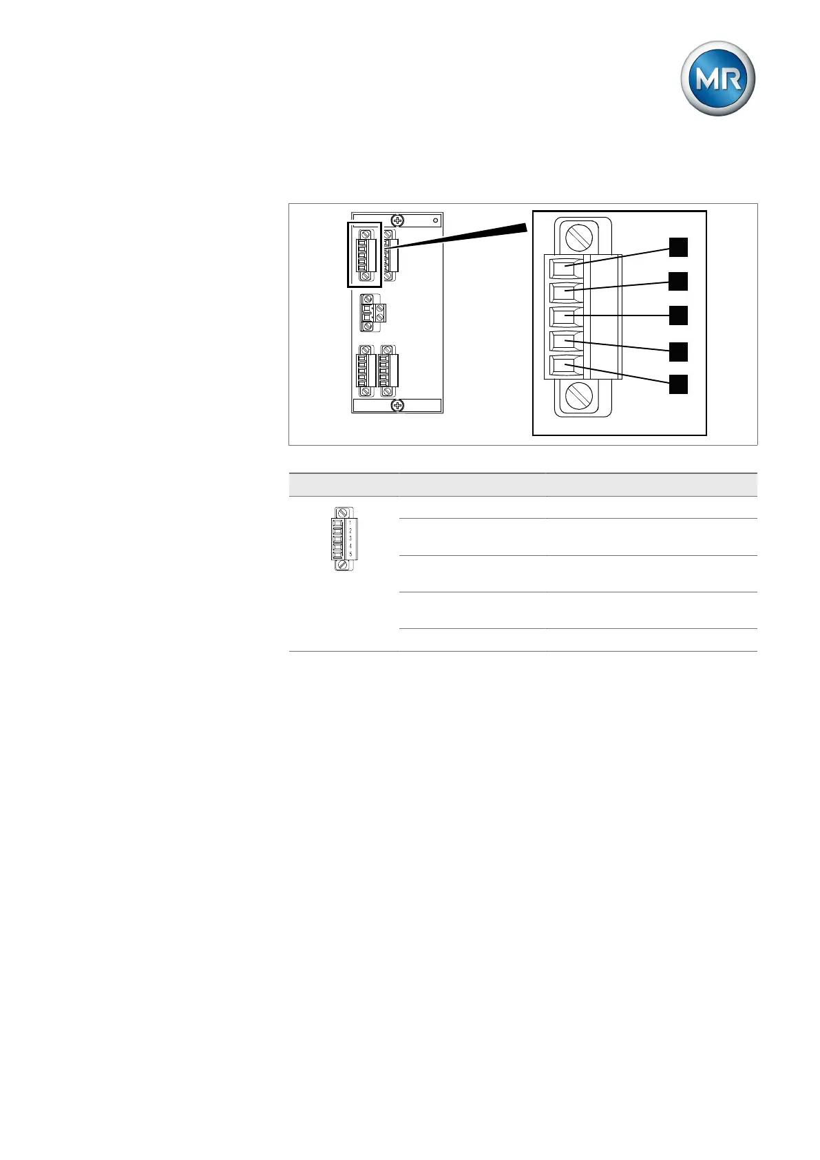
The AIO assembly has a separate plug connector for each channel (input or
output). The plugs are assigned as follows:
1
3
2
4
5
11
13
12
14
15
6
8
7
9
10
16
18
17
19
20
RDY
AIO
+
-
24V DC
1
3
2
4
5
1
2
3
4
5
Figure63: Plug assignment of the AIO module (illustration using module AIO4 as an example)
Interface Pin Description
1 6 11 16 I OUT (+): Current output +
2 7 12 17 I/U IN (+) U OUT (+): Voltage input
+, current input +, voltage output +
3 8 13 18 I/U IN (-): Voltage input -, current in-
put -
4 9 14 19 I/U OUT (-): Voltage output -, current
output -
5 10 15 20 Not used
Table14: Analog inputs and outputs
You can connect the following types of analog sensors:
▪ 4...20mA
▪ PT100/PT1000 (2-wire, 3-wire, 4-wire)