6 Checking and Adjustment
172 Pulse Laser Station NPL-302 Series Instruction Manual
Zero Point Errors of Vertical Scale and Horizontal
Angle Corrections 6.1
Checking 61.1
1. Set up the instrument on the tripod.
2. Follow the leveling procedures described in Leveling, page 16.
3. Flip the telescope to the Face-1 position.
4. Sight a target that is within 45° of the horizontal plane.
5. Read the vertical angle from the VA1 field in the Basic Measurement Screen
(BMS).
6. Rotate the instrument 180° and flip the telescope to the Face-2 position.
7. Read the vertical angle from the VA2 field.
8. Add the two vertical angles together, VA1 + VA2.
– No adjustment is required if the zero reference for vertical angles (VA zero
setting) is set to Zenith, and VA1 + VA2 equals 360°.
– No adjustment is required if the zero reference for vertical angles (VA zero
setting) is set to Horizon, and VA1 + VA2 is either 180° or 540°.
– An adjustment is required if VA1 + VA2 is not one of the values listed above.
Note – The difference between the vertical angle reading the relevant angle
(either 360° for Zenith, or 180° or 540° for Horizon) is called the altitude
constant.
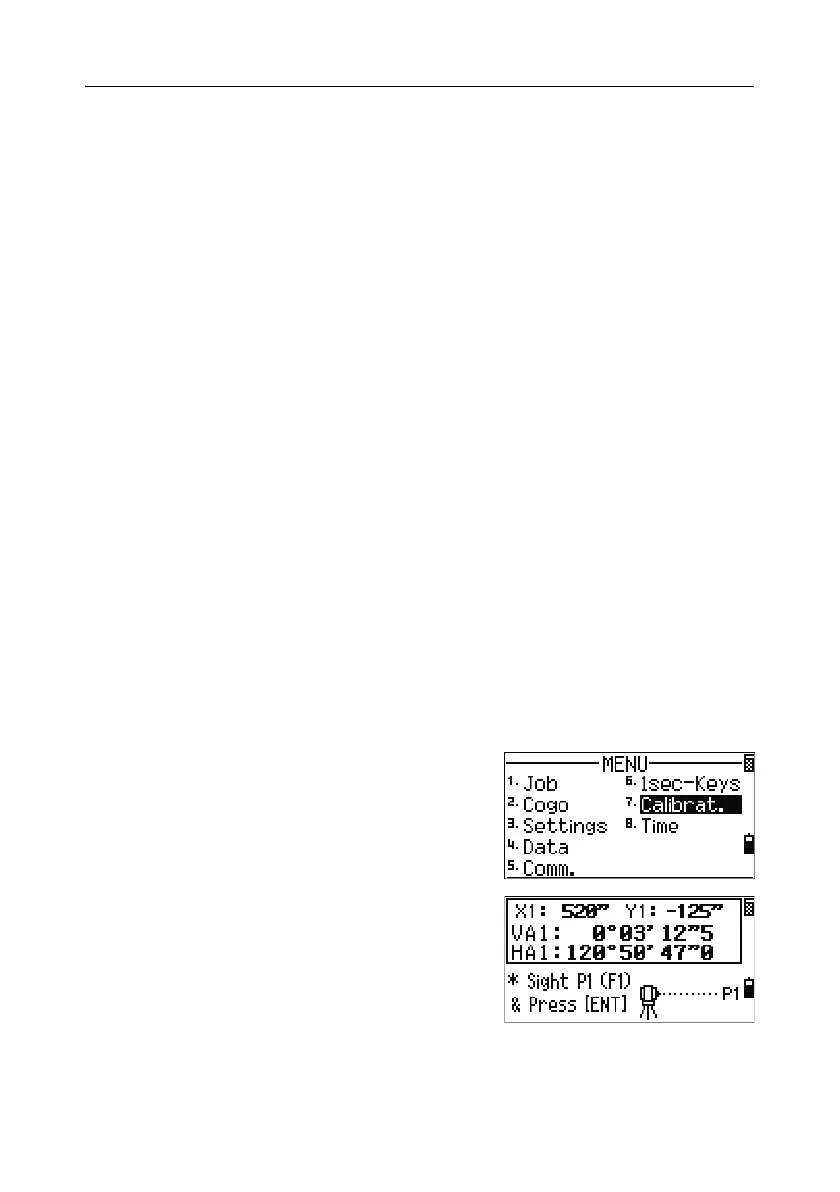
Adjusting 60.1
To enter the calibration screen, press [MENU] and
[7].
1. The NPL-362/352 has two-axis level
compensation. Take an F1 measurement to a
target on the horizon. Press
[ENT].
The vertical angle is shown in the
V0 dir= Horiz setting.
VA1 Face-1 vertical angle (tilt-off value)
HA1 Face-1 horizontal angle (tilt-off value)