Operation 6-11
3. Conveyor position controls (Figure 6-10) operate as follows:
! On the X-Y control panel, the arrows pointing to the
Left move the conveyor belt to the
left and the arrows pointing to the
Right move it to the right.
! On the X-Y control panel, the arrows pointing
Up move the rear rail toward the back of
the dispensing area and the arrows pointing
Down move the rear rail toward the front of
the dispensing area.
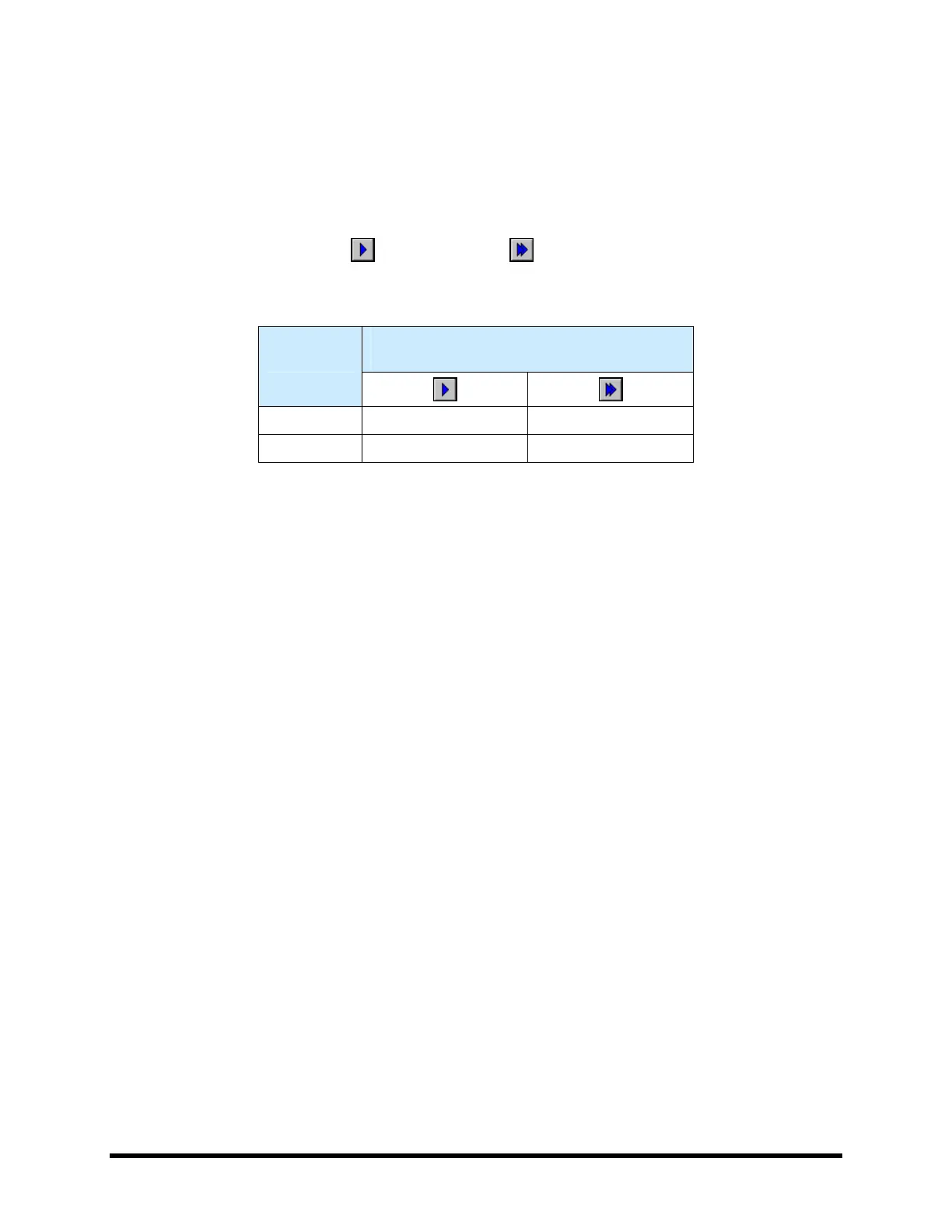
" NOTE The single arrows and double arrows
move the conveyor rail or belt different
distances per mouse click as specified in
Table 6-1.
Table 6-1 Conveyor Position Controls: Jog Distance
(1)
Distance
mm (inch)
(2)
Movement
Axis
Y 0.0254 (0.001) 1.27 (0.0500)
X 0.0254 (0.001) 1.27 (0.0500)
Notes: (1) Default distances. Refer to the Fluidmove User Guide or
Fluidmove Online Help to modify jog distances.
(2) Distance per mouse click on the arrow button.
4. Dispensing Head position controls (Figure 6-11) operate as follows:
! On the X-Y control panel, the arrows pointing to the
Left move the dispensing head to the
left and the arrows pointing to the
Right move it to the right.
! On the X-Y control panel, the arrows pointing
Up move the dispensing head toward the
back of the dispensing area and the arrows pointing
Down move it toward the front of the
dispensing area.
! On the Z-axis control panel, the arrows pointing
Up move the dispensing head upward
and the arrows pointing
Down move it downward.
" NOTE Refer to Table 6-3 for a detailed explanation of position control commands for both the
dispensing head and conveyor.
 Loading...


