CT Analyzer User Manual
150 OMICRON
Note: The results for R
p
, X
p
and L
p
(C
p
) are calculated using the parallel equivalent circuit diagram, the
results for R
s
, X
s
and L
s
(C
s
) are calculated using the serial equivalent circuit diagram.
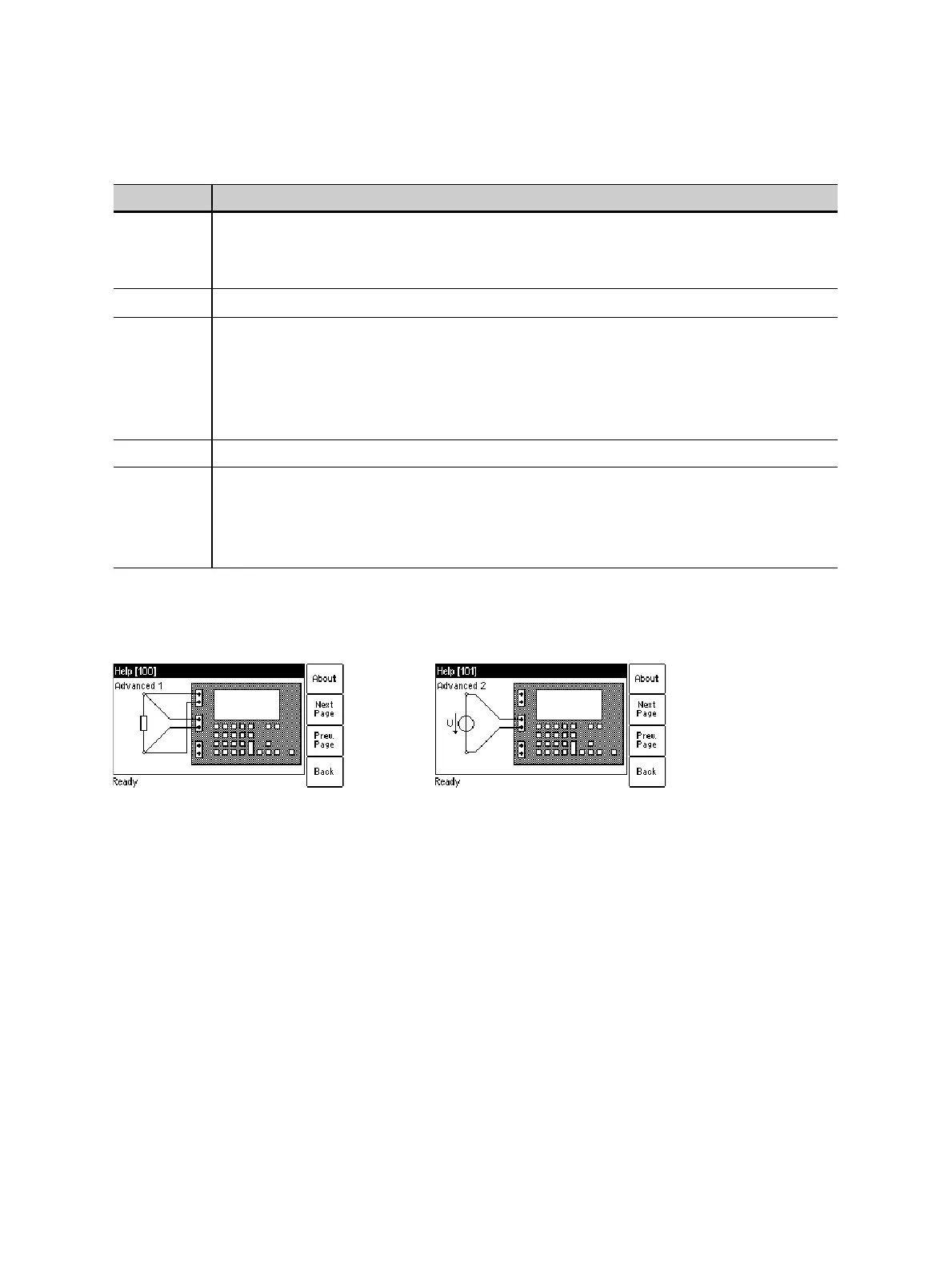
Use the following wiring (examples):
Figure 10-5: Wiring examples for Advanced measurement type
Xp, Xs Use the Xp/Xs soft key to switch between X
p
and X
s
.
Parallel or serial reactance, calculated from the output signal and the voltage measured
at input SEC.
cos
ϕ
Power factor of the measured impedance.
Lp, Ls or
Cp, Cs
Use the Lp/Ls (or Cp/Cs) soft key to switch between L
p
(C
p
) and L
s
(C
s
).
Parallel or serial inductance or capacitance of the test object, calculated from the output
signal and the voltage measured at input SEC.
CT Analyzer automatically detects whether the test object is an inductance or a
capacitance based on the phase angle.
f Frequency measured at input SEC.
Crest Out,
Crest Sec,
Crest Prim
Crest factor of the output signal or the signal measured at input SEC or input PRIM.
The crest factor is the peak/rms ratio of a waveform. For a sinusoidal waveform the
crest factor is 1.414 (√2). The crest factor may indicate possible signal distortion.
More detailed information can be found at http://en.wikipedia.org/wiki/Crest_factor.
Table 10-4: Results for Advanced measurement type (continued)
Result Description