OMICRON 85
Test cards for CT Test mode
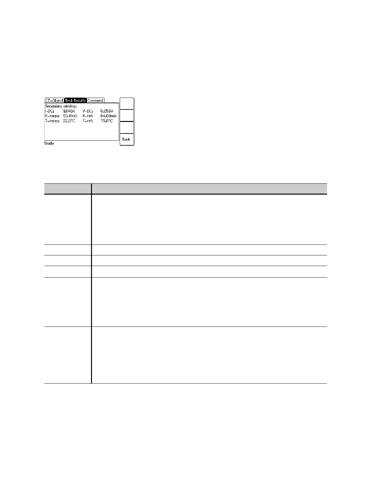
7.3.3 Secondary winding resistance measurement details
Press the Wdg. Res. Test soft key in the Test Results card to display the secondary winding resistance
measurement details.
Figure 7-5: Winding resistance measurement details
Table 7-7: Test results for secondary winding resistance measurement
Parameter Description
I-DC Current used for measurement. Selected automatically, cannot be changed by the
user.
If I
sn
is 0.2 A or higher, I
DC
is automatically set to I
sn
.
If I
sn
is lower than 0.2 A, I
DC
is automatically set to 0.2 A.
Maximum value: 5 A.
V-DC Measured voltage.
R-meas Measured resistance at ambient temperature.
R-ref Reference resistance (temperature-compensated resistance, compensated to T
ref
).
T-meas Winding temperature of the CT at the time of measurement.
Value used:
Ambient Temperature defined in the Settings (main menu).
If this temperature is not set correctly, the reference resistance value (R
ref
) at
reference temperature will not be calculated correctly.
T-ref Reference temperature, i.e, temperature the CT is specified for.
Value used:
Reference temperature defined in the Settings (main menu).
The winding resistance at reference temperature is calculated from the winding
resistance measured at ambient temperature (T
meas
) and the specified reference
temperature.