CT Analyzer User Manual
114 OMICRON
8.5.3 Test settings and results
The following settings are required to perform a winding resistance test.
The following parameters show the results of the winding resistance test after the test is finished.
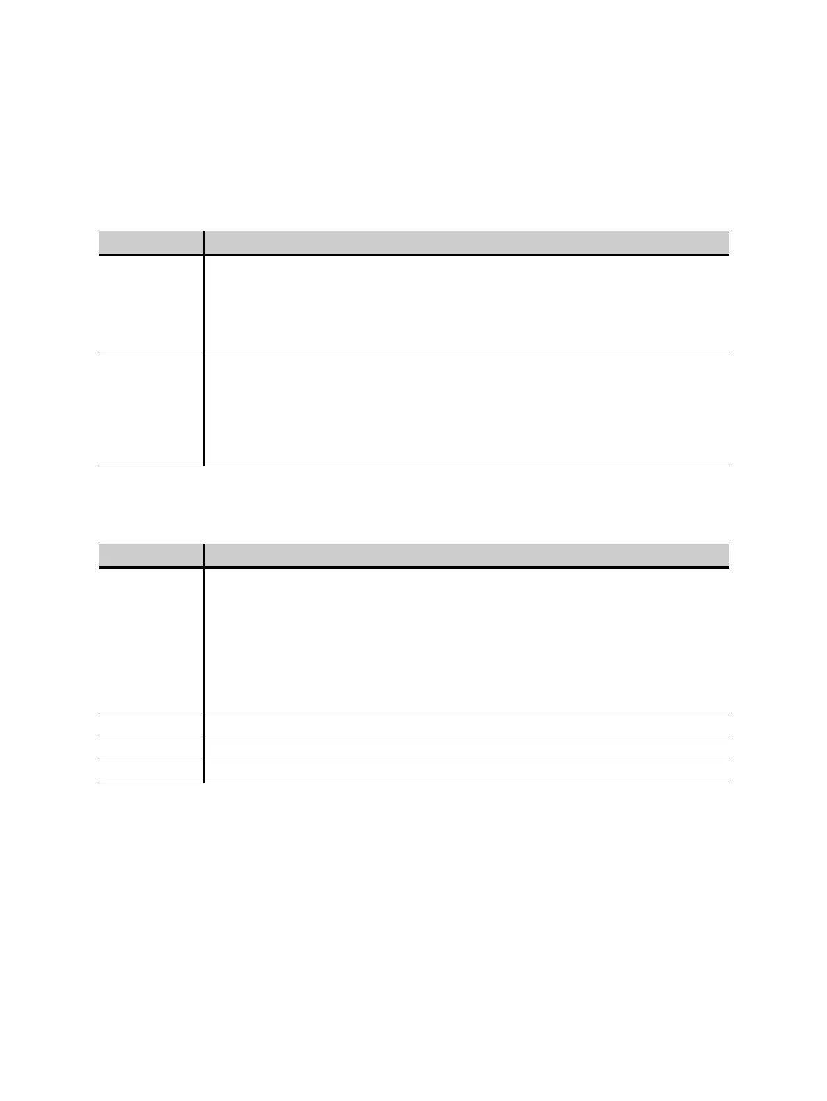
Table 8-15: Test settings for secondary winding resistance measurement
Parameter Description
T-meas Winding temperature of the CT at the time of measurement.
Value used:
Ambient Temperature defined in the Settings (main menu).
If this temperature is not set correctly, the reference resistance value (R
ref
) at reference
temperature will not be calculated correctly.
T-ref Reference temperature, i.e, temperature the CT is specified for.
Value used:
Reference temperature defined in the Settings (main menu).
The winding resistance at reference temperature is calculated from the winding
resistance measured at ambient temperature (T
meas
) and the specified reference
temperature.
Table 8-16: Test results for secondary winding resistance measurement
Parameter Description
I-DC Current used for measurement. Selected automatically, cannot be changed by the user.
Secondary winding resistance measurement only:
If I
sn
is 0.2 A or higher, I
DC
is automatically set to I
sn
.
If I
sn
is lower than 0.2 A, I
DC
is automatically set to 0.2 A.
Maximum value: 5 A.
Primary winding resistance measurement only:
Maximum value: 10 A.
V-DC Measured voltage.
R-meas Measured resistance at ambient temperature.
R-ref Reference resistance (temperature-compensated resistance, compensated to T
ref
).