OMICRON 31
Setup and connection
3.5 Connection for special applications
3.5.1 Measurement on a gapped core
Applicable for CT Test mode and Advanced CT Test mode.
For gapped cores, the position of the primary wire inside the core has a large influence on the ratio
measurement results.
Therefore, in order to obtain correct measurement results, it is very important to arrange the primary wire
during measurement to the same position inside the core as it is during real operation. Depending on the
position of the primary wire inside the core, the measured ratio can differ by up to 20%.
The figure below shows how the ratio error can differ depending on the position of the primary wire inside
the core.
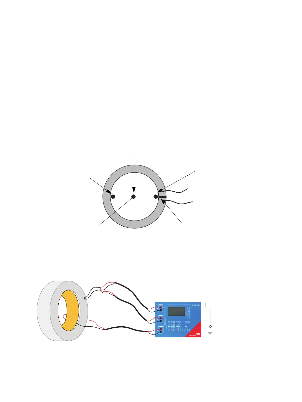
Figure 3-5: Ratio error depending on the position of the primary wire inside the gapped core
As shown in Figure 3-5, the measured ratio error may differ considerably depending on the position of
the primary wire. Best measurement results are obtained if the primary wire is positioned exactly to the
center of the core. As an alternative, a copper foil formed to a ring and placed to the inner side of the
core can be used as shown in Figure 3-6.
Figure 3-6: Using a copper foil formed to a ring as primary wire
Air gap
Position 2
Ratio error measured: +5%
Position 1
Ratio error measured: +0.5%
Position 3
Ratio error measured: -15%
Primary wire