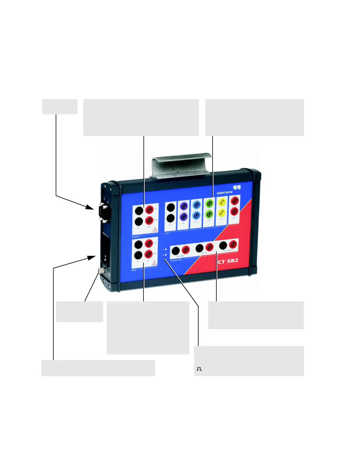
Equipotential
bonding connector
PRIM
IN: Measurement input for primary
side of the CT.
OUT: Generator output for primary
winding resistance
measurement.
A green LED lights up when the
output is active.
LEDs
I/0 Green power LED. Indicates that CT SB2 is
switched on and ready for operation.
Status LED.
Mains connection unit
Mains socket with fuse and ON/OFF switch
BURDEN
IN: Measurement input for burden measurement.
OUT: Generator output for burden measurement.
A green LED lights up when the output is active.
See also Figure 3-2
TAPS
Terminals for connection of CT taps X1 to X6.
Connect each CT tap to both sockets!
A green LED lights up to indicate which
input/output is currently active.
PC and CTA
interfaces
CT ANALYZER
Input and output terminals for connection to
the CT Analyzer measurement inputs and
generator output.