EasyManuals Logo

Omicron CT SB2 User Manual

Omicron CT SB2
252 pages
To Next Page IconTo Next Page
To Previous Page IconTo Previous Page
Page #201 background imageLoading...
Page #201 background image
OMICRON 13
Hardware
Figure 3-2: Side view of CT SB2 with mains connection unit, PC and CTA interfaces, and equipotential
bonding connector
3.2 Block diagram (simplified)
Figure 3-3: Simplified block diagram of CT SB2
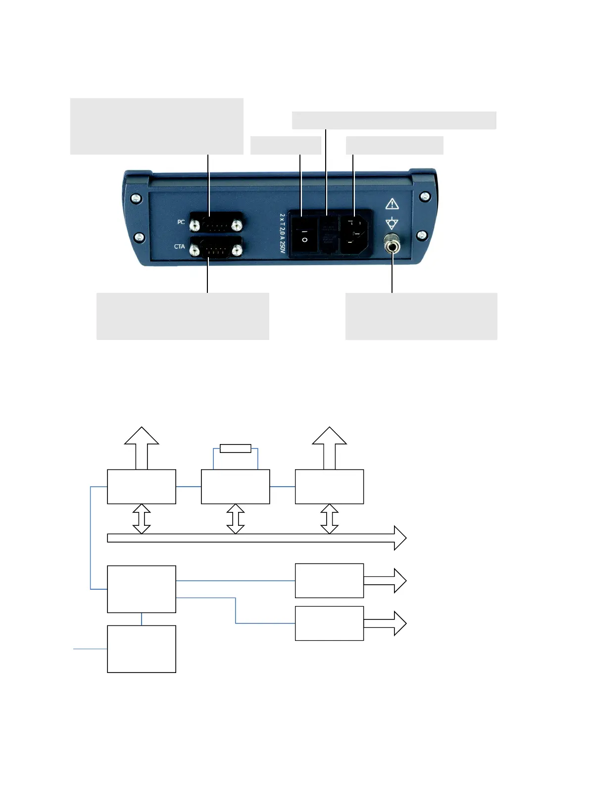
Mains socket (IEC320)ON/OFF switch
Equipotential bonding connector
(4mm socket combined with knurled nut
for clamp connection)
Mains fuse: 2 x T2.0A / 250V, high breaking capacity
PC interface
9-pole SUB-D connector, female.
Connection of CT SB2 to a PC (to serial COM
interface or USB interface via USB-serial
adapter).
CTA interface
9-pole SUB-D connector, male.
Connection of CT SB2 to the remote control
interface of CT Analyzer.
Power Supply
Mains
Control
RS232
RS232
CTA
CTA
PC
TAPS
Switching relays
BURDEN
Relays
PRIM
Relays
CT PRIM
CT SEC TAPS
BURDEN

Table of Contents

Other manuals for Omicron CT SB2

Questions and Answers:

Question and Answer IconNeed help?

Do you have a question about the Omicron CT SB2 and is the answer not in the manual?

Omicron CT SB2 Specifications

General IconGeneral
BrandOmicron
ModelCT SB2
CategoryMeasuring Instruments
LanguageEnglish

Related product manuals