CT Analyzer User Manual
170 OMICRON
12.4 Winding resistance measurement accuracy
12.5 Ratio and phase measurement accuracy
The values given in the following table are only valid under the following conditions:
• All utility lines to the primary side of the CT are disconnected.
• One terminal of the primary side of the CT is connected to PE.
• The original measurement cables delivered by OMICRON for CT Analyzer are used.
• The CT under test is a CT with a non-gapped core.
• The knee point voltage according to IEEE C57.13 is > 3V.
Under interfering conditions the device has reduced accuracy.
Values without the prefix "!" in the ratio table of the Ratio card have guaranteed accuracy. The accuracy
of values marked with a "!" in the table is reduced by factor 2 since these values are not directly
measured but calculated from the measured values instead.
Table 12-4: Measurement input PRIM
Characteristic Rating
Voltage ranges 0 - 0.03 / 0.3 / 3 / 30V
AC
(auto ranging)
Accuracy 0.1% (guaranteed)
Insulation Reinforced insulation (R) to all other circuits
Table 12-5: Winding resistance measurement accuracy
Characteristic Rating
Resolution
1m
Ω
Accuracy 0.05% (typical)
0.1% + 1m
Ω (guaranteed)
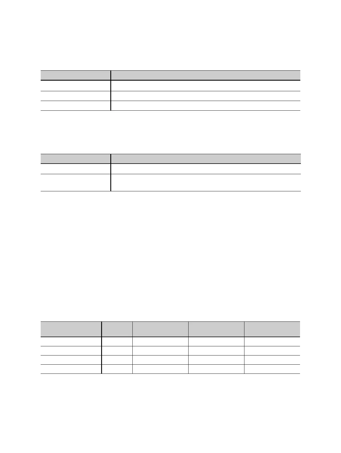
Table 12-6: Ratio measurement accuracy for 1 A CTs at rated current
CT ratio I
sn
Rated power
1
1. Nominal burden of the CT.
Typical accuracy Guaranteed
accuracy
0.2 - 1 1 1.0 - 30VA 0.05% 0.1%
> 1 - 2000 1 0 - 30VA 0.02% 0.05%
> 2000 - 5000 1 0 - 30VA 0.03% 0.1%
> 5000 - 10000 1 0 - 30VA 0.05% 0.2%