CT SB2 User Manual
24 OMICRON
5.2 Running the test
1. Start the test by pressing the key on CT Analyzer. The red LED on CT Analyzer flashes to
indicate that the CT test is running.
2. After starting the test, CT Analyzer first checks communication with the CT SB2 switch box via the
serial interface. CT Analyzer then checks the input/output wiring between CT Analyzer and CT SB2
and the corresponding wiring from CT SB2 to the test object. If CT Analyzer detects any missing or
faulty connections, a corresponding error message is displayed.
3. CT Analyzer measures the secondary winding resistance, the excitation curve, and the ratio of the
CT for each tap combination. The currently active input/output of the CT SB2 switch box is indicated
by a green LED on the CT SB2 front panel.
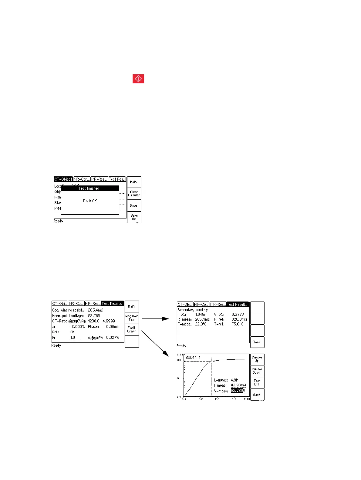
4. When the test is over, the red LED stops flashing and the green LED is on. CT Analyzer displays a
"Test finished" message showing the status of the test execution. The MR Test mode does not
provide automatic test assessment. Press any key on the keyboard to close this message.
Figure 5-3: Test finished message when the test is over
5.3 After the test is finished
1. Display the Test Results card to view the test results for the tap combination selected as tap in use
in the MR-Config. card prior to the test (refer to Figure 5-4).
Press Wdg. Res. Test to display the details of the winding resistance test and/or press Excit. Graph
to display the excitation graph (see also 8.4.3 on page 43 and 8.4.4 on page 44).
Figure 5-4: Test Results card after the test is finished