716
PLC Setup Appendix G
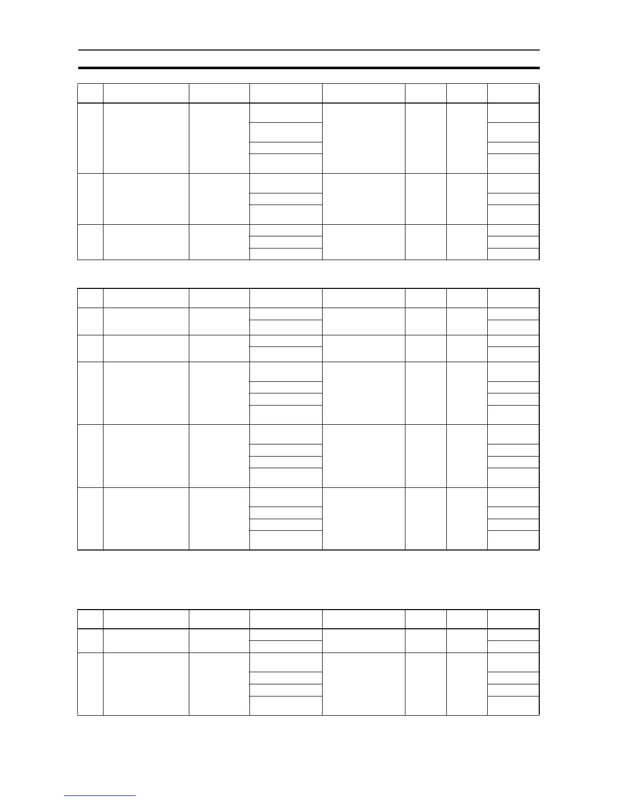
Operation Adjustment Settings
Inverter Positioning 1
Basic Settings
8 Error counter cycle 0: 3 (4-ms incre-
ments)
0: 3 (4-ms incre-
ments)
When power is turned
ON
417 00 to 07 00 hex
1 (4-ms incre-
ments)
01 hex
: :
255 (4-ms incre-
ments)
FF hex
9 Power Supply Freq. for
One Motor Revolution
per Sec.
0 (0.1-Hz incre-
ments)
0 (0.1-Hz incre-
ments)
When power is turned
ON
436 00 to 15 0000 hex
: :
65,535 Hz (0.1-Hz
increments)
FFFF hex
10 Number of Encoder
Pulses for One Motor
Revolution
0 0 When power is turned
ON
437 00 to 15 0000 hex
: :
65,535 FFFF hex
Name Default Settings When setting is read
by CPU Unit
Internal
address
Bits Settings
1 Limit output during
acceleration and con-
stant speed
Do not use Use When power is turned
ON
432 00 to 03 0 hex
Do not use 1 hex
2 Limit output during
deceleration and when
stopped
Do not use Use When power is turned
ON
432 04 to 07 0 hex
Do not use 1 hex
3 Output coefficient dur-
ing acceleration and
constant speed
0: 6 (0.01 incre-
ments)
0: 6 (0.01 incre-
ments)
When power is turned
ON
433 00 to 07 0 hex
1 (0.01 increments) 1 hex
: :
255 (0.01 incre-
ments)
FF hex
4 Output coefficient dur-
ing deceleration
0: 96 (0.01
increments)
0: 96 (0.01 incre-
ments)
When power is turned
ON
434 00 to 07 0 hex
1 (0.01 increments) 1 hex
: :
255 (0.01 incre-
ments)
FF hex
5 Output coefficient after
pulse output
0: 50 (0.01
increments)
0: 50 (0.01 incre-
ments)
When power is turned
ON
435 00 to 07 0 hex
1 (0.01 increments) 1 hex
: :
255 (0.01 incre-
ments)
FF hex
Name Default Settings When setting is read
by CPU Unit
Internal
address
Bits Settings
1 Use inverter positioning Do not use Use When power is turned
ON
416 08 to 11 0 hex
Do not use 1 hex
2 Gain 0: 10 (0.1 incre-
ments)
0: 10 (0.1 incre-
ments)
When power is turned
ON
425 00 to 15 0000 hex
1 (0.1 increments) 0001 hex
: :
65,535
(0.1 increments)
FFFF hex
Name Default Settings When setting is read
by CPU Unit
Internal
address
Bits Settings

 Loading...


