75
High-speed Counter Board Section 2-1
External outputs 1 to 4 are controlled by ORs performed on corresponding
bits (i.e., bits with the same bit number) in the comparison result bits 08 to 11
for high-speed counters 1 to 4. The user must determine which outputs
should be turned ON for each possible comparison result and set the bit pat-
terns so that the OR operations will produce the desired result.
Note Range Comparison Flags are supported by the built-in high-speed counter
(high-speed counter 0) and the Pulse I/O Board for ranges1 to 8. These flags,
however, are not supported by the High-speed Counter Board. The internal bit
patterns must be used to produce the same type of output result.
Reading High-speed
Counter Status
The following two methods can be used to read the status of high-speed
counters 1 to 4:
• Using CPU Unit memory words
• Using PRV(62)
Using CPU Unit Memory Words
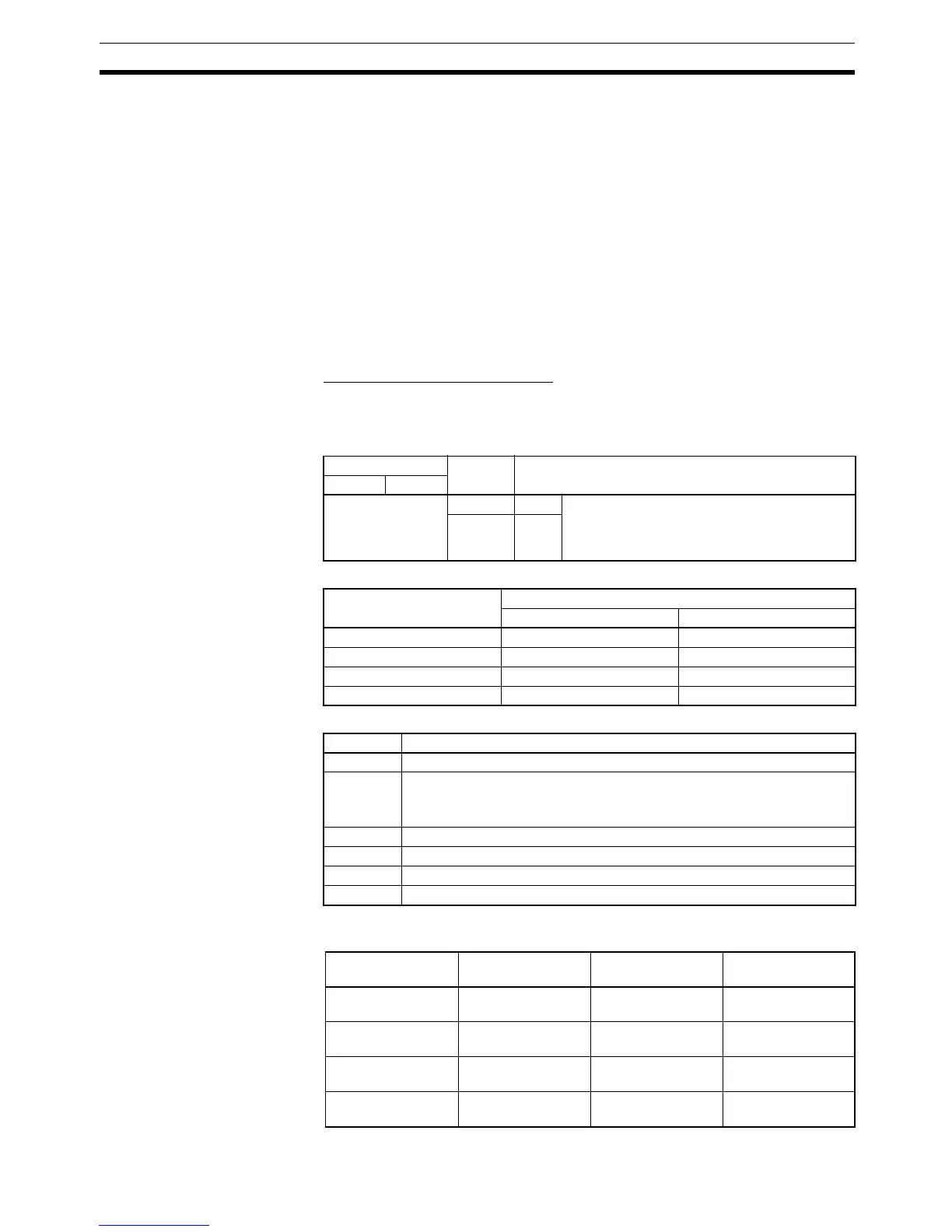
The memory area words and bits in the CPU Unit that indicate the status of
high-speed counters 1 to 4 are given below.
Inner Board Error Codes
Operating Status Words
The functions of the bits in each operating status word are as follows:
Note The following table shows the relationship between external outputs 1 to 4
and Comparison Results External Output Bits.
Word Bits Function
Slot 1 Slot 2
AR 04 00 to 07 Slot 1 The following 2-digit error codes are stored.
00 Hex: Normal
01 or 02 Hex: Hardware error
03 Hex: PC Setup error
08 to 15 Slot 2
High-speed counter Word
Slot 1 Slot 2
High-speed counter 1 IR 208 IR 240
High-speed counter 2 IR 209 IR 241
High-speed counter 3 IR 210 IR 242
High-speed counter 4 IR 211 IR 243
Bits Function
00 to 07 Comparison Results: Internal Output Bits
08 to 11 Comparison Results: External Output Bits for Outputs 1 to 4
The result of an OR operation on bits in same bit positions for all the
high-speed counters 1 to 4 will be output. (See note.)
12 Counter Operating Flag (0: Stopped; 1: Running)
13 Comparison Flag (0: Stopped; 1: Running)
14 PV Overflow/Underflow Flag (0: No; 1: Yes)
15 SV Error Flag (0: Normal; 1: Error)
High-speed
counter
External output Slot 1 Slot 2
Counter 1 External output 1 OR of bits 08 of
IR 208 to IR 211
OR of bits 08 of
IR 240 to IR 241
Counter 2 External output 2 OR of bits 09 of
IR 208 to IR 211
OR of bits 09 of
IR 240 to IR 241
Counter 3 External output 3 OR of bits 10 of
IR 208 to IR 211
OR of bits 10 of
IR 240 to IR 241
Counter 4 External output 4 OR of bits 11 of
IR 208 to IR 211
OR of bits 11 of
IR 240 to IR 241