EasyManuals Logo

Omron CQM1H - PROGRAM User Manual

Omron CQM1H - PROGRAM
602 pages
To Next Page IconTo Next Page
To Previous Page IconTo Previous Page
Page #163 background imageLoading...
Page #163 background image
138
Analog I/O Board Section 2-5
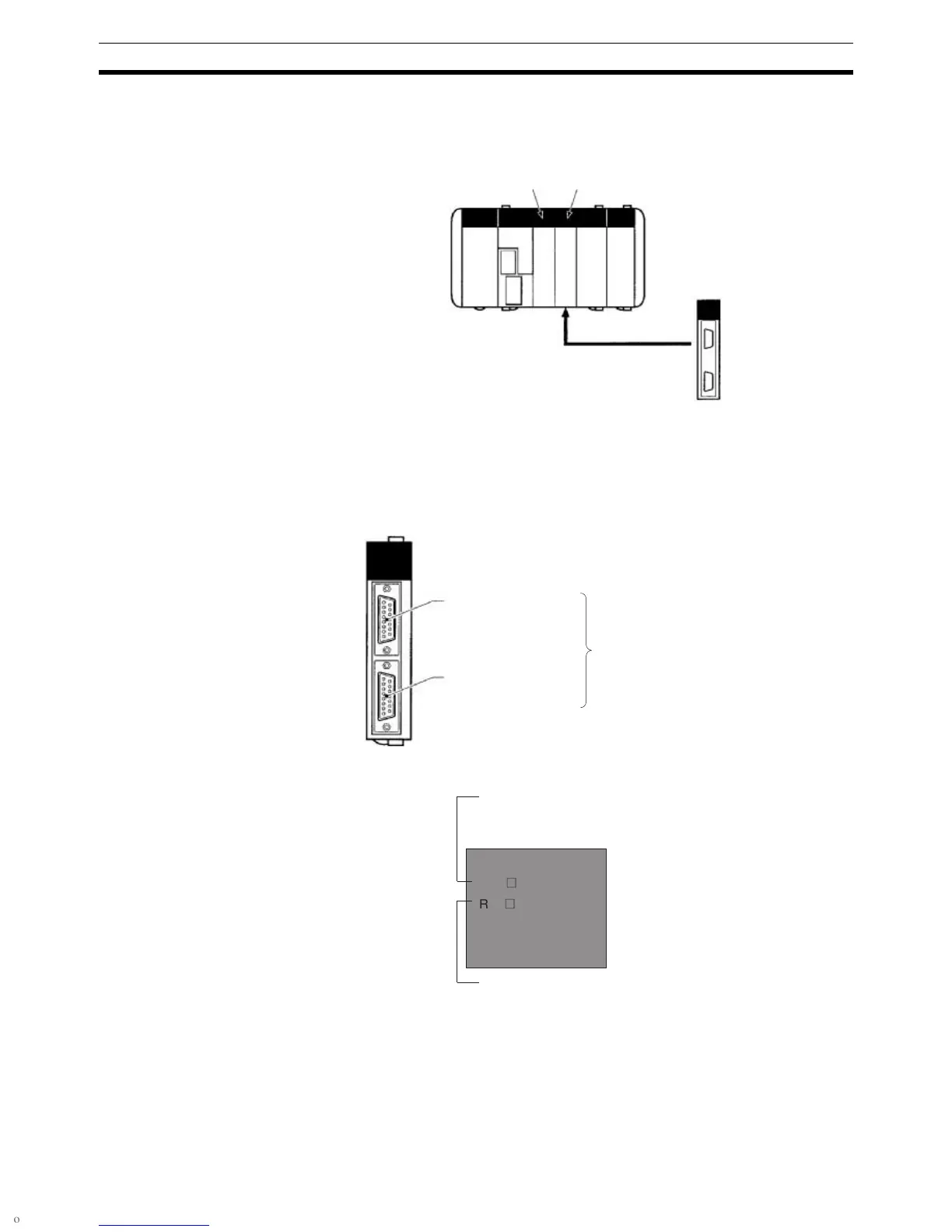
2-5-4 Applicable Inner Board Slot
The Analog I/O Board can only be mounted in slot 2 (right slot) of the
CQM1H-CPU51/61 CPU Unit.
2-5-5 Names and Functions
The Analog I/O Board has a CN1 connector for the four analog inputs and a
CN2 connector for 2 analog outputs.
LED Indicators
Slot 1: No Slot 2: OK
CQM1H-MAB42
Analog I/O Board
CN1
Analog inputs 1 to 4
CN2
Analog outputs 1 to 2
Compatible connector
Socket: XM2D-1501 (OMRON)
Hood: XM2S-1511 (OMRON)
Two Socket+Hood sets are pro-
vided as standard accessories.
RDY (Green)
Lit when analog I/O can be performed.
ERR (Red)
Lit when there is an error in the PC Set-
up for analog I/O, or when an error has
occurred during analog conversion.
ERR
(
RDY
(

Table of Contents

Questions and Answers:

Question and Answer IconNeed help?

Do you have a question about the Omron CQM1H - PROGRAM and is the answer not in the manual?

Omron CQM1H - PROGRAM Specifications

General IconGeneral
I/O CapacityUp to 512 points
Power Supply100 to 240 VAC, 50/60 Hz or 24 VDC (depending on model)
Instruction SetBasic and advanced instructions
Operating Temperature0 to 55°C
Program Capacity7.2K to 15.2K steps
Communication PortsRS-232C
Expansion SlotsUp to 3 expansion units
TypeProgrammable Logic Controller (PLC)
CPU TypeRISC
Program Memory7.2K to 15.2K steps
I/O Points512 max
Expansion CapabilityUp to 3 expansion units
Data MemoryRAM (battery backup)

Related product manuals