65
High-speed Counter Board Section 2-1
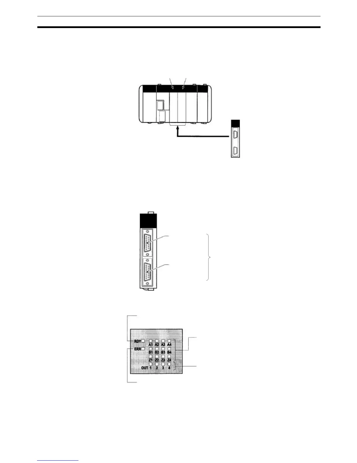
2-1-4 Applicable Inner Board Slots
The High-speed Counter Board can be installed in either slot 1 (left slot) or
slot 2 (right slot) of the CQM1H-CPU51/61 CPU Unit. Both slots can be used
at the same time.
2-1-5 Names and Functions
One High-speed Counter Board provides two connectors that accept high-
speed pulse inputs. CN1 is used for inputs 1 and 2, and CN2 is used for inputs
3 and 4.
LED Indicators
High-speed Counter Board
Slot 1 Slot 2
CQM1H-CTB41 High-speed Counter Board
CN1
Pulse input 1
Pulse input 2
CN2
Pulse input 3
Pulse input 4
Compatible connector
Socket: XM2D-1501 (OMRON)
Hood: XM2S-1511 (OMRON)
Two Socket+Hood sets are provided as
standard accessories.
RDY: Operational (Green)
Lit when pulse inputs can be received.
Pulse Inputs (Orange)
A1, A2, A3, A4:
Lit when phase-A input is ON in port 1, 2, 3, or 4.
B1, B2, B3, B4:
Lit when phase-B input is ON in port 1, 2, 3, or 4.
Z1, Z2, Z3, Z4:
Lit when phase-Z input is ON in port 1, 2, 3, or 4.
ERR: Error (Red)
Lit when an error is detected in the PC Setup settings for the input pulse
function, or when an overflow or underflow occurs in the high-speed count-
er's present value.
External Outputs (Orange)
OUT1, OUT2, OUT3, OUT4:
Lit when the corresponding output (1, 2, 3, or 4) is ON.