EasyManuals Logo

Omron CQM1H - PROGRAM User Manual

Omron CQM1H - PROGRAM
602 pages
To Next Page IconTo Next Page
To Previous Page IconTo Previous Page
Page #148 background imageLoading...
Page #148 background image
123
Absolute Encoder Interface Board Section 2-3
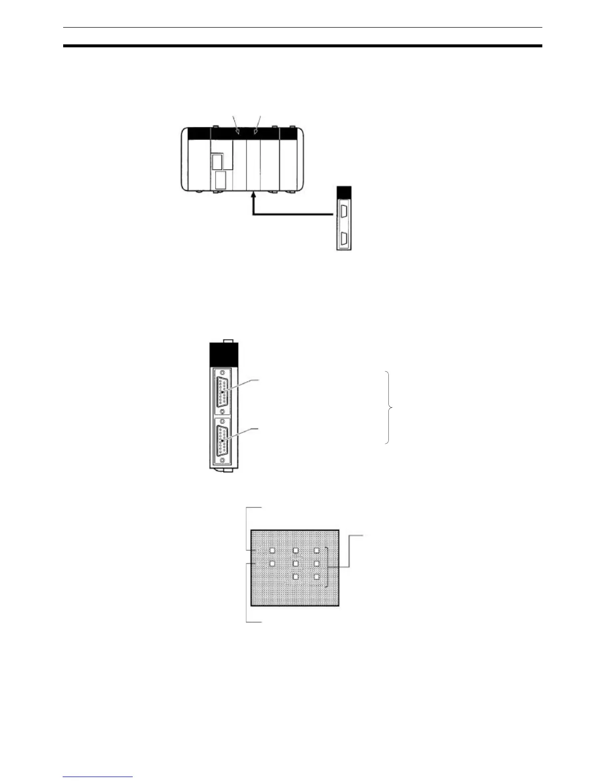
2-3-4 Applicable Inner Board Slots
The Absolute Encoder Interface Board can only be mounted in slot 2 (right
slot) of the CQM1-CPU51/61 CPU Unit.
2-3-5 Names and Functions
The Absolute Encoder Interface Board is provided with port 1 connector CN1
and port 2 connector CN2 to receive binary gray code input from absolute
rotary encoders.
LED Indicators
Slot 1: No
Absolute Encoder
Interface Board
Slot 2: OK
CQM1H-ABS02
CN1
Input from absolute encoder 1
Compatible connector
Socket: XM2D-1501 (OMRON)
Hood: XM2S-1511 (OMRON)
Two Socket+Hood sets are provided
as standard accessories.
CN2
Input from absolute encoder 2
Ready (green)
Lit when the Absolute Encoder Interface Board is ready.
Error (red)
Lit when there is an error in the PC Setup for the Absolute
Encoder Interface Board.
Encoder input (orange)
Refer to the following table.
RDY
ERR
IN1 IN2
INC1 INC2
DEC1 DEC2

Table of Contents

Questions and Answers:

Question and Answer IconNeed help?

Do you have a question about the Omron CQM1H - PROGRAM and is the answer not in the manual?

Omron CQM1H - PROGRAM Specifications

General IconGeneral
I/O CapacityUp to 512 points
Power Supply100 to 240 VAC, 50/60 Hz or 24 VDC (depending on model)
Instruction SetBasic and advanced instructions
Operating Temperature0 to 55°C
Program Capacity7.2K to 15.2K steps
Communication PortsRS-232C
Expansion SlotsUp to 3 expansion units
TypeProgrammable Logic Controller (PLC)
CPU TypeRISC
Program Memory7.2K to 15.2K steps
I/O Points512 max
Expansion CapabilityUp to 3 expansion units
Data MemoryRAM (battery backup)

Related product manuals