402
Special Instructions Section 5-28
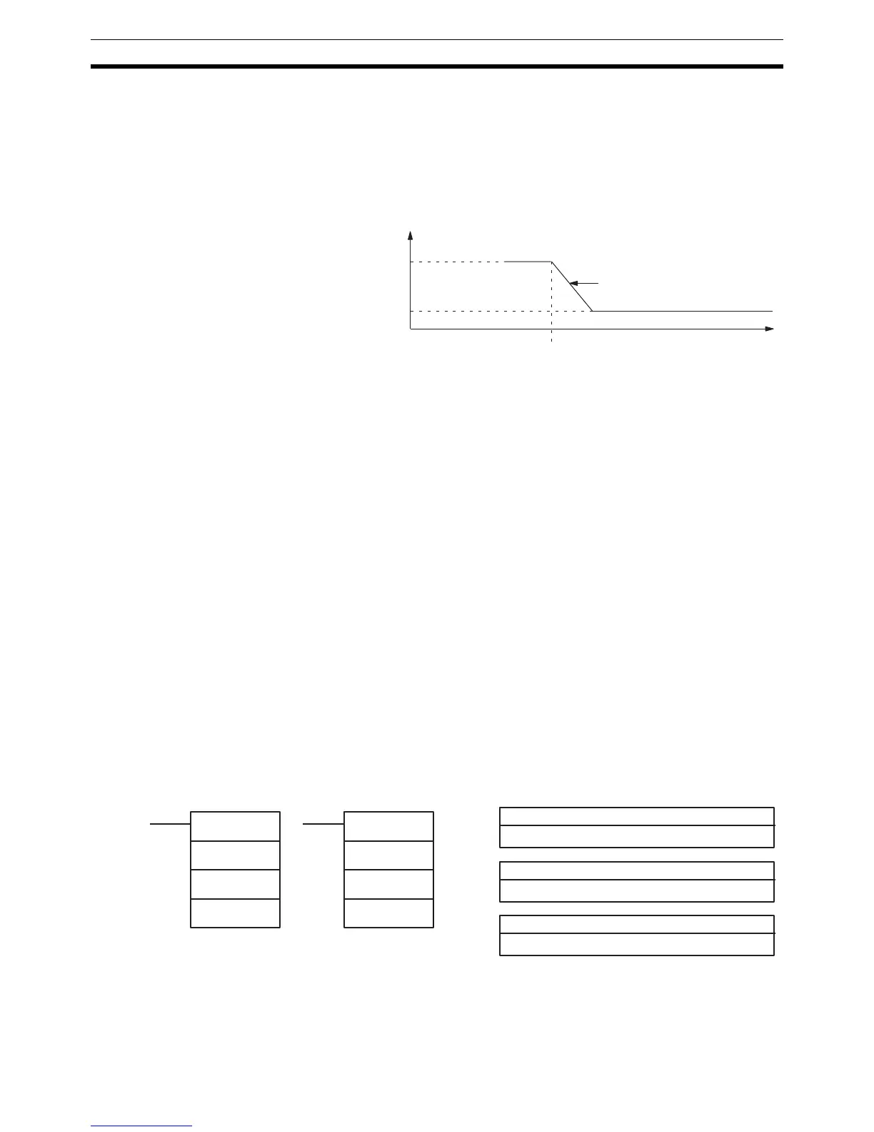
1,2,3... 1. The content of C determines the deceleration rate. During deceleration,
the output frequency is decreased by the amount set in C every 4.08 ms.
C must be BCD from 0001 to 0200 (10 Hz to 2 kHz).
2. The content of C+1 specifies the target frequency. C+1 must be BCD from
0000 to 5000 (0 Hz to 50 kHz).
Mode 3 (M=003) Mode 3 is used to decrease the frequency being output to a target frequency
at the specified rate. Pulse output continues until stopped.
The 2 control words indicate the acceleration rate and target frequency.
1,2,3... 1. The content of C determines the acceleration rate. During acceleration, the
output frequency is increased by the amount set in C every 4.08 ms. C
must be BCD from 0001 to 0200 (10 Hz to 2 kHz).
2. The content of C+1 specifies the target frequency. C+1 must be BCD from
0000 to 5000 (0 Hz to 50 kHz).
Flags ER: Indirectly addressed EM/DM word is non-existent.
(Content of *EM/*DM word is not BCD, or the EM/DM area boundary
has been exceeded.)
There is an error in the operand settings.
ACC(––) is executed without a Pulse I/O Board installed.
The PC Setup is not set for pulse output.
ACC(––) is executed with M=000 and the specified output port is al-
ready in use.
ACC(––) is executed in an interrupt subroutine while a pulse I/O or
high-speed counter instruction is being executed in the main program.
AR 0515: Port 1 output flag. ON when pulses are being output from port 1.
AR 0615: Port 2 output flag. ON when pulses are being output from port 2.
5-28-13 PULSE WITH VARIABLE DUTY FACTOR – PWM(––)
Limitations PWM(––) cannot be used unless the PC Setup (DM 6643 or DM 6644) is set
for variable duty factor pulse outputs.
P must be 001 or 002 and F must be 000, 001, or 002.
D must be BCD between 0001 and 0099.
Target frequency
Deceleration rate
Frequency before
deceleration
Execution of ACC(−−)
P: Communications port
001 or 002
Ladder Symbols Operand Data Areas
@PWM(−− )
P
F
D
D: Duty factor
IR, SR, AR, DM, EM, HR, TIM/CNT, LR, #
F: Frequency
000, 001, or 002
PWM(−− )
P
F
D