EasyManua.ls Logo

Omron CQM1H - PROGRAM User Manual

Omron CQM1H - PROGRAM
602 pages
To Next Page IconTo Next Page
To Previous Page IconTo Previous Page
Page #264 background imageLoading...
Page #264 background image
239
Timer and Counter Instructions Section 5-16
If #0001 is set, the Completion Flag may turn ON as soon as the timer’s
execution condition turns ON because timer accuracy is 0 to –0.01 s.
Consider the timer accuracy (0 to –0.01 s) when determining the proper set
value.
Flags ER: SV is not in BCD.
Indirectly addressed EM/DM word is non-existent.
(Content of *EM/*DM word is not BCD, or the EM/DM area boundary
has been exceeded.)
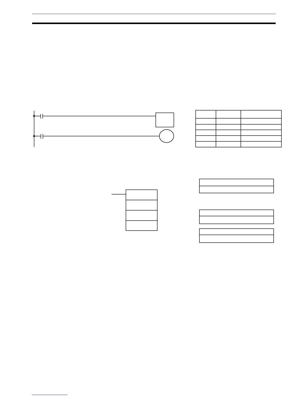
Example The following example shows a timer set with a constant. 01600 will be turned
ON after 00000 goes ON and stays ON for at least 1.5 seconds. When 00000
goes OFF, the timer will be reset and 01600 will be turned OFF.
5-16-5 TOTALIZING TIMER – TTIM(––)
Limitations SV is between 0000 and 9999 and must be in BCD. The decimal point is not
entered.
The EM area is available in CQM1H-CPU61 CPU Units only.
Each TIM/CNT number can be used as the definer in only one TIMER or
COUNTER instruction.
Description TTIM(––) is used to create a timer that increments the PV every 0.1 s to time
between 0.1 and 999.9 s. TTIM(––) increments in units of 0.1 second from
zero. TTIM(––) accuracy is +0.0/–0.1 second. A TTIM(––) timer will time as
long as its execute condition is ON until it reaches the SV or until RB turns ON
to reset the timer. TTIM(––) timers will time only as long as they are executed
every cycle, i.e., they do not time, but maintain the current PV, in interlocked
program sections or when they are jumped in the program.
Note The PVs of decrementing timers such as TIM indicate the time remaining until
the timer times out, but the PVs of TTIM(––) timers indicate the time that has
elapsed. The TTIM(––) PV can be used “as is” to represent the elapsed time
in calculations and displays.
01600
00000
TIM 000
01.50 s
000
#0150
TIMH(15)
Address Instruction Operands
00000 LD 00000
00001 TIMH(15) 000
# 0150
00002 LD TIM 000
00003 OUT 01600
SV: Set value (word, BCD)
IR, AR, DM, EM, HR, LR
RB: Reset bit
IR, SR, AR, HR, LR
Ladder Symbol
Operand Data Areas
TTIM(−− )
N
SV
RB
N: TIM/CNT number
# (000 through 511)
Definer Values

Table of Contents

Question and Answer IconNeed help?

Do you have a question about the Omron CQM1H - PROGRAM and is the answer not in the manual?

Omron CQM1H - PROGRAM Specifications

General IconGeneral
I/O CapacityUp to 512 points
Power Supply100 to 240 VAC, 50/60 Hz or 24 VDC (depending on model)
Instruction SetBasic and advanced instructions
Operating Temperature0 to 55°C
Program Capacity7.2K to 15.2K steps
Communication PortsRS-232C
Expansion SlotsUp to 3 expansion units
TypeProgrammable Logic Controller (PLC)
CPU TypeRISC
Program Memory7.2K to 15.2K steps
I/O Points512 max
Expansion CapabilityUp to 3 expansion units
Data MemoryRAM (battery backup)

Summary

PRECAUTIONS

1 Intended Audience

Specifies the target personnel for this manual, requiring knowledge of electrical systems and FA systems.

2 General Precautions

Outlines user responsibilities for operating the product according to specifications and consulting representatives for specific applications.

3 Safety Precautions

Details critical safety warnings related to I/O refreshing, touching internal components, disassembly, and power supply handling.

5 Application Precautions

Provides essential safety guidelines for using the PC System, including grounding, power handling, and unit mounting.

SECTION 1 PC Setup and Other Features

1-1 PC Setup

Explains operating parameters for CQM1H control, including default values and how to change them.

SECTION 2 Inner Boards

2-1 High-speed Counter Board

Describes the functions, input modes, comparison operations, and external outputs of the High-speed Counter Board.

2-2 Pulse I/O Board

Details the Pulse I/O Board's support for two pulse inputs and two pulse outputs, including input modes and interrupts.

SECTION 3 Memory Areas

3-1 Memory Area Structure

Explains the memory areas used by the CQM1H PC, including IR, Work, Controller Link status, MACRO operand, Inner Board, Analog, High-speed Counter, and EM areas.

SECTION 4 Ladder-diagram Programming

4-1 Basic Procedure

Outlines the fundamental steps for writing a program, including obtaining I/O lists and drawing ladder diagrams.

4-4 Controlling Bit Status

Details instructions for controlling individual bit status: OUTPUT, OUTPUT NOT, SET, RESET, DIFFERENTIATE UP/DOWN, KEEP.

4-6 Programming Precautions

Provides essential precautions for drawing clear ladder diagrams and inputting programs, emphasizing instruction order and TR bits.

4-7 Program Execution

Describes the CPU Unit's program scan from top to bottom, checking conditions, and executing instructions.

SECTION 5 Instruction Set

SECTION 6 Host Link Commands

6-1 Host Link Command Summary

Provides a summary table of Host Link commands available for CQM1H communications.

6-4 Command and Response Formats

Details the formats for commands issued from the host computer and responses received from the PC.

6-5 Host Link Commands

Lists and describes various Host Link commands for reading and writing data in IR, SR, LR, HR, DM, EM, and AR areas.

SECTION 7 CPU Unit Operation and Processing Time

7-1 CPU Unit Operation

Explains the overall operation flowchart of the CQM1H CPU Unit and defines cycle time.

7-2 Power Interruptions

Details the CPU Unit's behavior during power interruptions and momentary power supply failures.

7-3 Cycle Time

Explains the processes involved in a single execution cycle and their respective processing times.

SECTION 8 Troubleshooting

8-2 Programming Console Operation Errors

Lists common error messages encountered when using the Programming Console and their appropriate responses.

Appendix A Programming Instructions

5-8 Ladder Diagram Instructions

Explains basic instructions like LOAD, AND, OR, and their combinations, including logic block instructions.

5-9 Bit Control Instructions

Covers instructions for controlling individual bit status: OUT, OUT NOT, SET, RESET, DIFU, DIFD, KEEP.

5-14 User Error Instructions: FAILURE ALARM AND RESET – FAL(06) and SEVERE FAILURE ALARM – FALS(07)

Describes instructions for outputting error numbers for operation, maintenance, and debugging, including non-fatal and fatal errors.

5-16 Timer and Counter Instructions

Details instructions for managing timers and counters, including TIM, TIMH, CNT, CNTR, TTIM, STIM, and CTBL.

5-29 Network Instructions

Explains instructions for communicating with other PCs via the Controller Link System, including SEND, RECV, and CMND.

5-30 Communications Instructions

Details instructions for serial communications, including RECEIVE (RXD), TRANSMIT (TXD), CHANGE SERIAL PORT SETUP (STUP), and PROTOCOL MACRO (PMCR).

Related product manuals