EasyManua.ls Logo

Omron CQM1H - PROGRAM User Manual

Omron CQM1H - PROGRAM
602 pages
To Next Page IconTo Next Page
To Previous Page IconTo Previous Page
Page #254 background imageLoading...
Page #254 background image
229
JUMP and JUMP END – JMP(04) and JME(05) Section 5-13
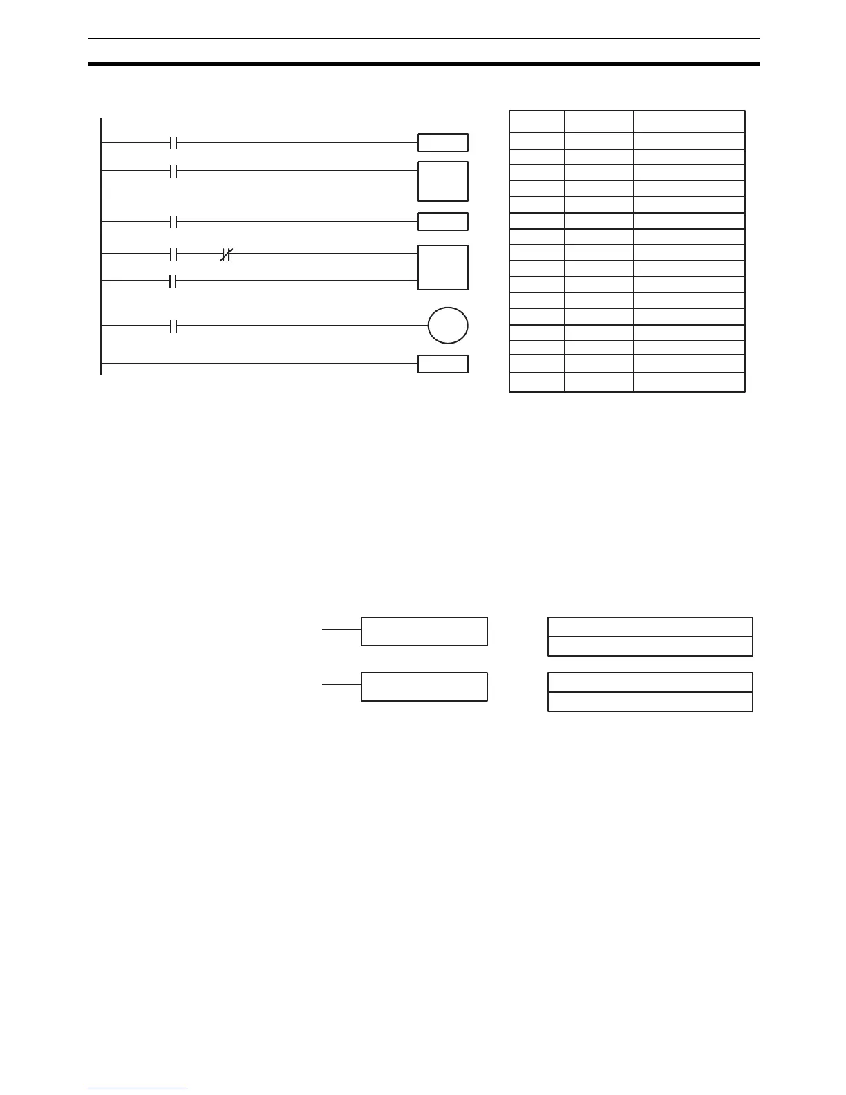
Example The following diagram shows IL(02) being used twice with one ILC(03).
When the execution condition for the first IL(02) is OFF, TIM 127 will be reset
to 1.5 s, CNT 001 will not be changed, and 00502 will be turned OFF. When
the execution condition for the first IL(02) is ON and the execution condition
for the second IL(02) is OFF, TIM 127 will be executed according to the status
of 00001, CNT 001 will not be changed, and 00502 will be turned OFF. When
the execution conditions for both the IL(02) are ON, the program will execute
as written.
5-13 JUMP and JUMP END – JMP(04) and JME(05)
Limitations Jump numbers 01 through 99 may be used only once in JMP(04) and once in
JME(05), i.e., each can be used to define one jump only. Jump number 00 can
be used as many times as desired.
Jump numbers run from 00 through 99.
Description JMP(04) is always used in conjunction with JME(05) to create jumps, i.e., to
skip from one point in a ladder diagram to another point. JMP(04) defines the
point from which the jump will be made; JME(05) defines the destination of
the jump. When the execution condition for JMP(04) is ON, no jump is made
and the program is executed consecutively as written. When the execution
condition for JMP(04) is OFF, a jump is made to the JME(05) with the same
jump number and the instruction following JME(05) is executed next.
If the jump number for JMP(04) is between 01 and 99, jumps, when made, will
go immediately to JME(05) with the same jump number without executing any
instructions in between. The status of timers, counters, bits used in OUT, bits
used in OUT NOT, and all other status bits controlled by the instructions
between JMP(04) and JMP(05) will not be changed. Each of these jump num-
Address Instruction Operands
00000 LD 00000
00001 IL(02)
00002 LD 00001
00003 TIM 127
# 0015
00004 LD 00002
00005 IL(02)
00006 LD 00003
00007 AND NOT 00004
00008 LD 00100
00009 LD 00100
00010 CNT 001
010
00011 LD 00005
00012 OUT 00502
00013 ILC(03)
00000
00001
ILC(03)
IL(02)
00004
00005
00003
00002
IL(02)
00502
CP
R
CNT
001
IR 010
00100
001.5 s
TIM 127
#0015
N: Jump number
#
Ladder Symbols Definer Values
JMP(04) N
N: Jump number
#
JME(05) N

Table of Contents

Question and Answer IconNeed help?

Do you have a question about the Omron CQM1H - PROGRAM and is the answer not in the manual?

Omron CQM1H - PROGRAM Specifications

General IconGeneral
I/O CapacityUp to 512 points
Power Supply100 to 240 VAC, 50/60 Hz or 24 VDC (depending on model)
Instruction SetBasic and advanced instructions
Operating Temperature0 to 55°C
Program Capacity7.2K to 15.2K steps
Communication PortsRS-232C
Expansion SlotsUp to 3 expansion units
TypeProgrammable Logic Controller (PLC)
CPU TypeRISC
Program Memory7.2K to 15.2K steps
I/O Points512 max
Expansion CapabilityUp to 3 expansion units
Data MemoryRAM (battery backup)

Summary

PRECAUTIONS

1 Intended Audience

Specifies the target personnel for this manual, requiring knowledge of electrical systems and FA systems.

2 General Precautions

Outlines user responsibilities for operating the product according to specifications and consulting representatives for specific applications.

3 Safety Precautions

Details critical safety warnings related to I/O refreshing, touching internal components, disassembly, and power supply handling.

5 Application Precautions

Provides essential safety guidelines for using the PC System, including grounding, power handling, and unit mounting.

SECTION 1 PC Setup and Other Features

1-1 PC Setup

Explains operating parameters for CQM1H control, including default values and how to change them.

SECTION 2 Inner Boards

2-1 High-speed Counter Board

Describes the functions, input modes, comparison operations, and external outputs of the High-speed Counter Board.

2-2 Pulse I/O Board

Details the Pulse I/O Board's support for two pulse inputs and two pulse outputs, including input modes and interrupts.

SECTION 3 Memory Areas

3-1 Memory Area Structure

Explains the memory areas used by the CQM1H PC, including IR, Work, Controller Link status, MACRO operand, Inner Board, Analog, High-speed Counter, and EM areas.

SECTION 4 Ladder-diagram Programming

4-1 Basic Procedure

Outlines the fundamental steps for writing a program, including obtaining I/O lists and drawing ladder diagrams.

4-4 Controlling Bit Status

Details instructions for controlling individual bit status: OUTPUT, OUTPUT NOT, SET, RESET, DIFFERENTIATE UP/DOWN, KEEP.

4-6 Programming Precautions

Provides essential precautions for drawing clear ladder diagrams and inputting programs, emphasizing instruction order and TR bits.

4-7 Program Execution

Describes the CPU Unit's program scan from top to bottom, checking conditions, and executing instructions.

SECTION 5 Instruction Set

SECTION 6 Host Link Commands

6-1 Host Link Command Summary

Provides a summary table of Host Link commands available for CQM1H communications.

6-4 Command and Response Formats

Details the formats for commands issued from the host computer and responses received from the PC.

6-5 Host Link Commands

Lists and describes various Host Link commands for reading and writing data in IR, SR, LR, HR, DM, EM, and AR areas.

SECTION 7 CPU Unit Operation and Processing Time

7-1 CPU Unit Operation

Explains the overall operation flowchart of the CQM1H CPU Unit and defines cycle time.

7-2 Power Interruptions

Details the CPU Unit's behavior during power interruptions and momentary power supply failures.

7-3 Cycle Time

Explains the processes involved in a single execution cycle and their respective processing times.

SECTION 8 Troubleshooting

8-2 Programming Console Operation Errors

Lists common error messages encountered when using the Programming Console and their appropriate responses.

Appendix A Programming Instructions

5-8 Ladder Diagram Instructions

Explains basic instructions like LOAD, AND, OR, and their combinations, including logic block instructions.

5-9 Bit Control Instructions

Covers instructions for controlling individual bit status: OUT, OUT NOT, SET, RESET, DIFU, DIFD, KEEP.

5-14 User Error Instructions: FAILURE ALARM AND RESET – FAL(06) and SEVERE FAILURE ALARM – FALS(07)

Describes instructions for outputting error numbers for operation, maintenance, and debugging, including non-fatal and fatal errors.

5-16 Timer and Counter Instructions

Details instructions for managing timers and counters, including TIM, TIMH, CNT, CNTR, TTIM, STIM, and CTBL.

5-29 Network Instructions

Explains instructions for communicating with other PCs via the Controller Link System, including SEND, RECV, and CMND.

5-30 Communications Instructions

Details instructions for serial communications, including RECEIVE (RXD), TRANSMIT (TXD), CHANGE SERIAL PORT SETUP (STUP), and PROTOCOL MACRO (PMCR).

Related product manuals