10
Inner Board Settings Section 1-2
1-2-2 Settings for a High-speed Counter Board
The settings in DM 6602, DM 6640, and DM 6641 determine the operation of
a High-speed Counter Board mounted in Inner Board slot 1.
The settings in DM 6611, DM 6643, and DM 6644 determine the operation of
a High-speed Counter Board mounted in Inner Board slot 2.
Note 1. The settings for the high-speed counter input mode are as follows:
2. The settings for the high-speed counter count frequency, numeric range,
and counter reset mode are as follows:
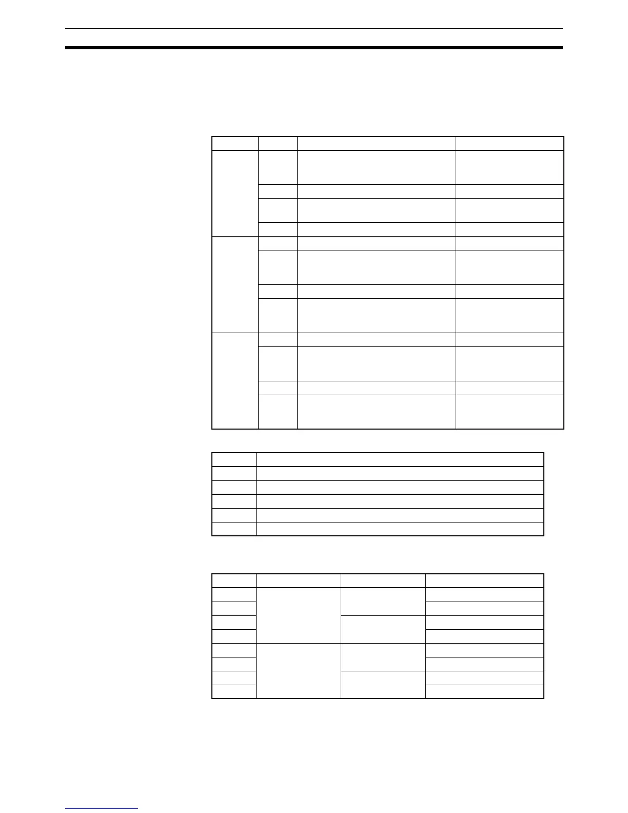
Word Bits Function Settings
DM 6602
(Slot 1)
DM 6611
(Slot 2)
00 High-speed Counter PV Data Format OFF: 8-digit hexadeci-
mal
ON: 8-digit BCD
01 to 07 Not used Set to 0.
08 External Output Transistor Selector OFF: Sourcing
ON: Sinking
09 to 15 Not used. Set to 0.
DM 6640
(Slot 1)
DM 6643
(Slot 2)
00 to 03 High-speed Counter 1 Input Mode See note 1.
04 to 07 High-speed Counter 1 Count Fre-
quency, Numeric Range, and
Counter Reset Mode
See note 2.
08 to 11 High-speed Counter 2 Input Mode See note 1.
12 to 15 High-speed Counter 2 Count Fre-
quency, Numeric Range, and
Counter Reset Mode
See note 2.
DM 6641
(Slot 1)
DM 6644
(Slot 2)
00 to 03 High-speed Counter 3 Input Mode See note 1.
04 to 07 High-speed Counter 3 Count Fre-
quency, Numeric Range, and
Counter Reset Mode
See note 2.
08 to 11 High-speed Counter 4 Input Mode See note 1.
12 to 15 High-speed Counter 4 Count Fre-
quency, Numeric Range, and
Counter Reset Mode
See note 2.
Setting Input Mode
0 Hex Differential Phase Inputs, 1x
1 Hex Differential Phase Inputs, 2x
2 Hex Differential Phase Inputs, 4x
3 Hex Up/Down Input
4 Hex Pulse/Direction Input
Setting Count frequency Numeric range Reset mode
0 Hex 50 kHz Linear Counting Phase-Z + Software Reset
1 Hex Software Reset Only
2 Hex Ring Counting Phase-Z + Software Reset
3 Hex Software Reset Only
4 Hex 500 kHz Linear Counting Phase-Z + Software Reset
5 Hex Software Reset Only
6 Hex Ring Counting Phase-Z + Software Reset
7 Hex Software Reset Only