398
Special Instructions Section 5-28
5-28-11 PULSE OUTPUT – PLS2(––)
Limitations PLS2(––) cannot be used if the PC Setup (DM 6611) is set to high-speed
counter mode.
P must be 001 or 002 and D must be 000 or 001.
C to C+3 must be in the same data area.
Description PLS2(––) can be used with the functions listed in the following table.
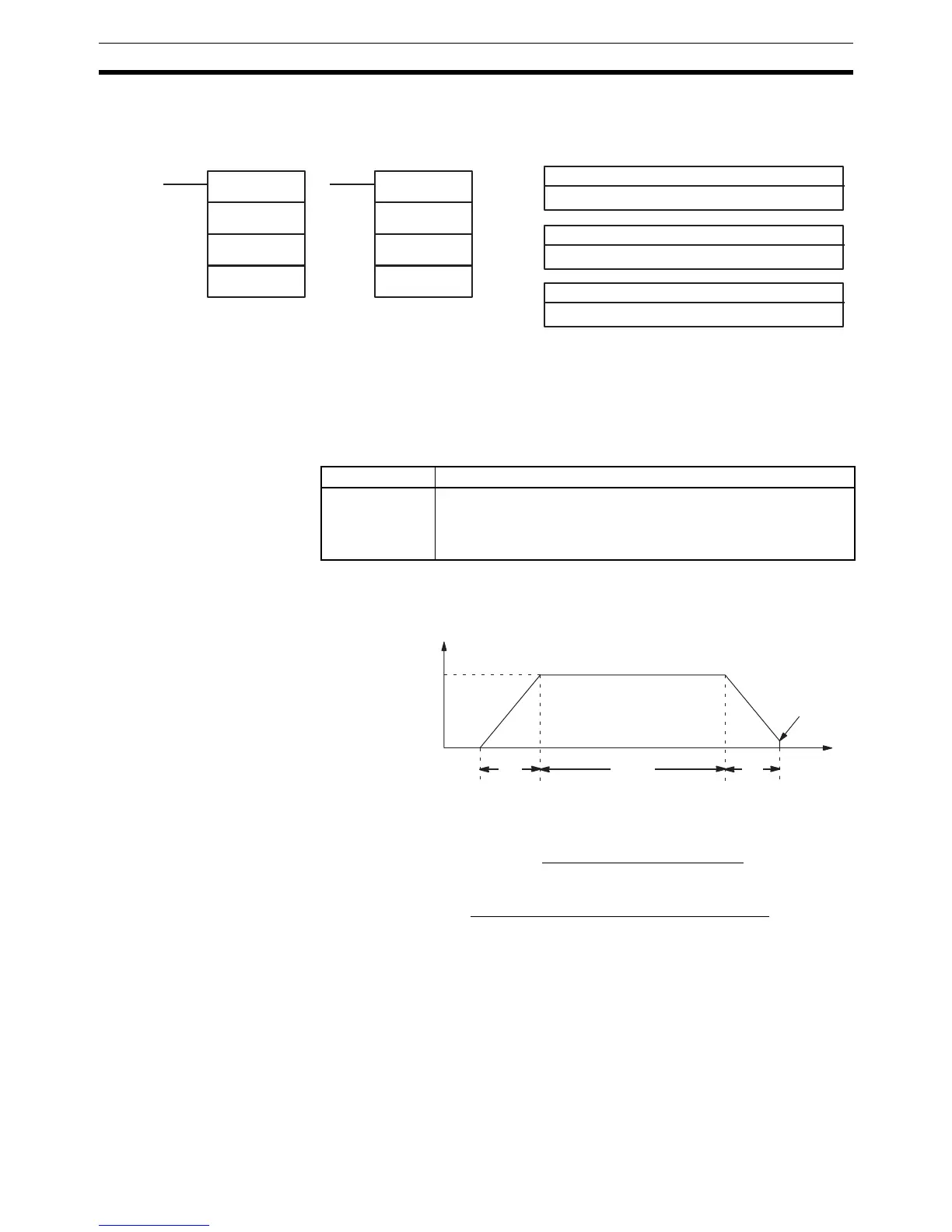
PLS2(––) is used to output a specified number of CW or CCW pulses from
port 1 or 2. The pulse output accelerates to the target frequency at a specified
rate and decelerates at the same rate. (Pulse output stops at 100 Hz.)
The following equations show how to calculate the approximate acceleration/
deceleration time T
1
and running time T
2
. Both times are in seconds.
Note 1. Although T
1
and T
2
will vary slightly depending on the operating condi-
tions, the number of pulses output will be accurate.
2. PLS2(––) will not operate if pulses are already being output from the spec-
ified port. Check the pulse output flags (AR 0515 for port 1 and AR 0615
for port 2) before executing PLS2(––).
3. Refer to 1-5 Pulse Output Function for more details.
P: Communications port
001 or 002
Ladder Symbols Operand Data Areas
@PLS2(−− )
P
D
C
C: First control word
IR, SR, AR, DM, EM, HR, LR
D: Direction specifier
000 or 001
PLS2(−− )
P
D
C
Unit/Board Function
Pulse I/O Board Pulse outputs 1 and 2
(The mode for ports 1 and 2 must be set to the simple positioning
mode in DM 6611 of the PC Setup. PLS2(––) cannot be used if the
mode is set to high-speed counter mode.)
Target frequency
T
1
T
1
T
2
100 Hz
T
1
≅ 0.0004 ×
Acceleration/deceleration rate
Target frequency
T
2
≅
Number of pulses – (T
1
× Target frequency)
Target frequency