159
IR Area Section 3-2
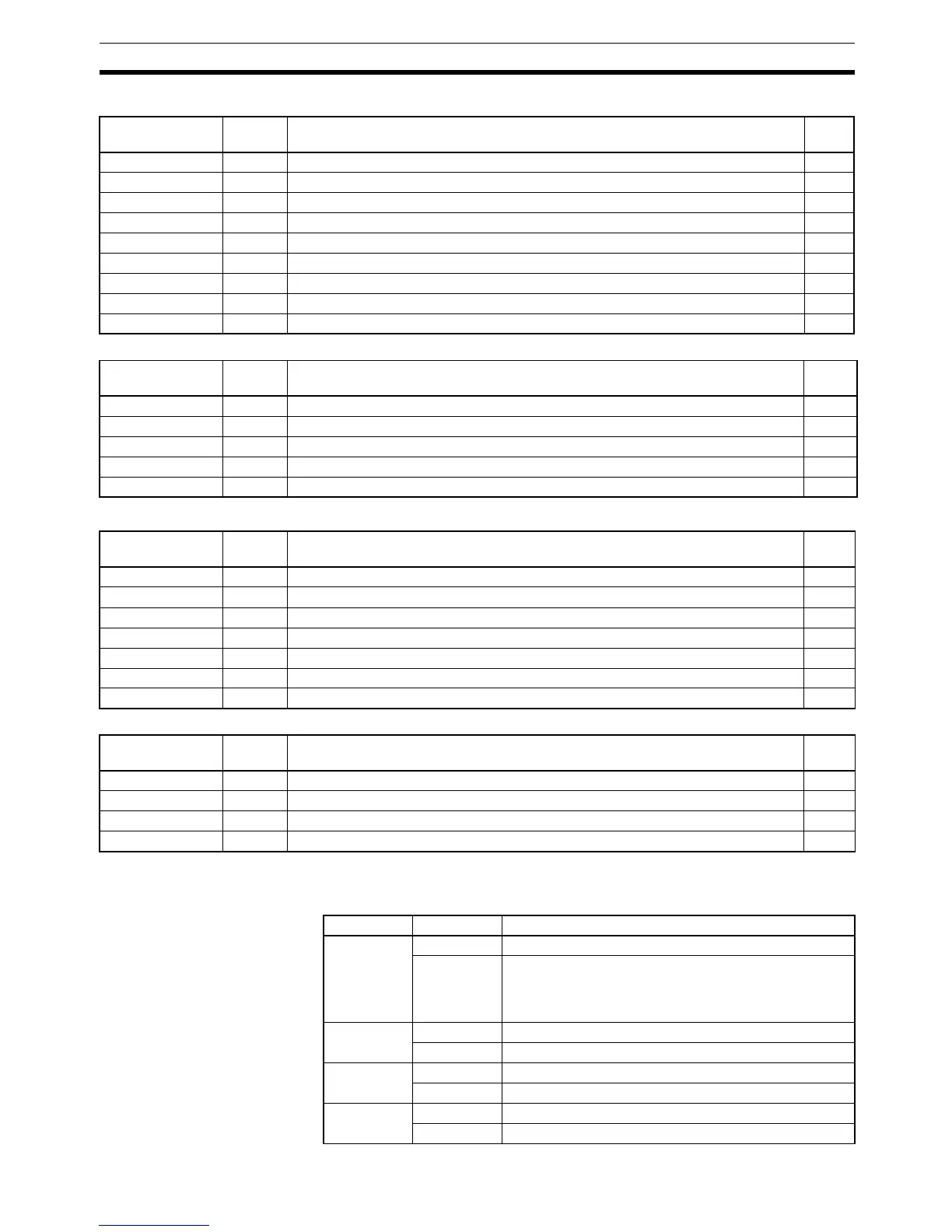
Pulse I/O Board Flags/Bits
Absolute Encoder Interface Board Flags/Bits
Analog I/O Board Flags/Bits
Analog Setting Board (Slot 1 and 2) Flags/Bits
3-2-6 Flags/Bits for Communications Units
Controller Link Status
Area 1 (IR 090 to IR 095)
Word Bits Function Read/
Write
IR 232 00 to 15 High-speed Counter 1 PV (rightmost 4 digits) R
IR 233 00 to 15 High-speed Counter 1 PV (leftmost 4 digits) R
IR 234 00 to 15 High-speed Counter 2 PV (rightmost 4 digits) R
IR 235 00 to 15 High-speed Counter 2 PV (leftmost 4 digits) R
IR 236 00 to 15 Port 1 Pulse Output PV (rightmost 4 digits) R
IR 237 00 to 15 Port 1 Pulse Output PV (leftmost 4 digits) R
IR 238 00 to 15 Port 2 Pulse Output PV (rightmost 4 digits) R
IR 239 00 to 15 Port 2 Pulse Output PV (leftmost 4 digits) R
IR 240 to IR 243 00 to 15 Not used. ---
Word Bits Function Read/
Write
IR 232 00 to 15 Absolute Encoder High-speed Counter 1 PV (rightmost 4 digits) R
IR 233 00 to 15 Absolute Encoder High-speed Counter 1 PV (leftmost 4 digits) R
IR 234 00 to 15 Absolute Encoder High-speed Counter 2 PV (rightmost 4 digits) R
IR 235 00 to 15 Absolute Encoder High-speed Counter 2 PV (leftmost 4 digits) R
IR 236 to IR 243 00 to 15 Not used. ---
Word Bits Function Read/
Write
IR 232 00 to 15 Analog Input 1 Conversion Value R
IR 233 00 to 15 Analog Input 2 Conversion Value R
IR 234 00 to 15 Analog Input 3 Conversion Value R
IR 235 00 to 15 Analog Input 4 Conversion Value R
IR 236 00 to 15 Analog Output 1 SV W
IR 237 00 to 15 Analog Output 2 SV W
IR 238 to IR 243 00 to 15 Not used. ---
Word Bits Function Read/
Write
IR 220 00 to 15 Analog SV 1: 0000 to 0200 (4-digit BCD) R
IR 221 00 to 15 Analog SV 2: 0000 to 0200 (4-digit BCD) R
IR 222 00 to 15 Analog SV 3: 0000 to 0200 (4-digit BCD) R
IR 223 00 to 15 Analog SV 4: 0000 to 0200 (4-digit BCD) R
Word Bits Function
IR 090 00 to 14 Always 0
15 Local Node’s Data Link Participation Status
0: The local node not in the Data Link or Data Link is
stopped.
1: The local node is participating in the Data Link.
IR 091 00 to 07 Data Link Status: Node 1
08 to 15 Data Link Status: Node 2
IR 092 00 to 07 Data Link Status: Node 3
08 to 15 Data Link Status: Node 4
IR 093 00 to 07 Data Link Status: Node 5
08 to 15 Data Link Status: Node 6