170
AR Area Section 3-6
3-6-4 Using the Clock
The CQM1H PCs can be equipped with a clock by installing a Memory Cas-
sette with a clock. This section explains how to use the clock.
There is an “R” at the end of the model number of Memory Cassettes with a
built-in clock. For example, the CQM1-ME04R Memory Cassette has a built-in
clock. The R comes from “real-time clock.”
Note The clock will stop and the current date and time clock data will be lost if the
Memory Cassette is removed from the CPU Unit.
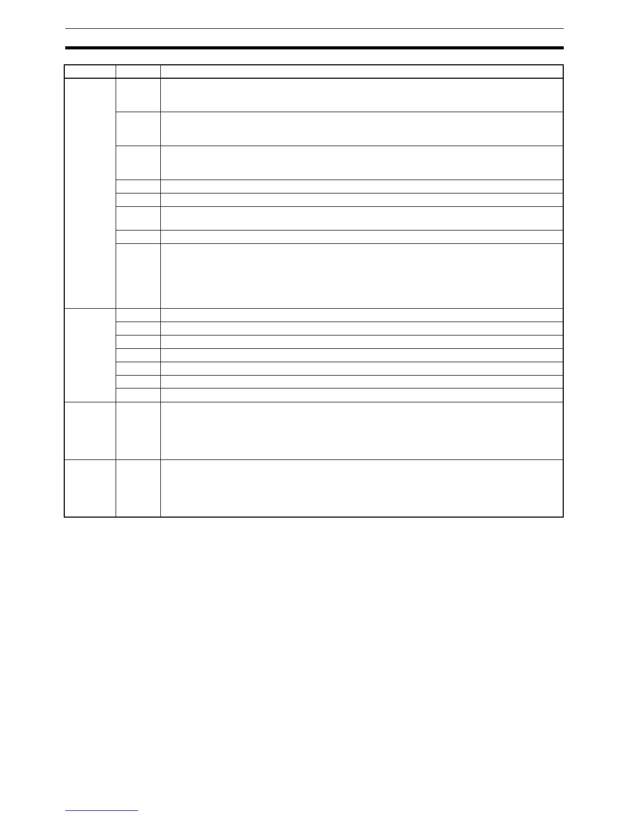
AR 24 00 Power-up PC Setup Error Flag
Turns ON when there is an error in DM 6600 to DM 6614 (the part of the PC Setup area that is
read at power-up).
01 Startup PC Setup Error Flag
Turns ON when there is an error in DM 6615 to DM 6644 (the part of the PC Setup area that is
read at the beginning of operation).
02 RUN PC Setup Error Flag
Turns ON when there is an error in DM 6645 to DM 6655 (the part of the PC Setup area that is
always read).
03 CPU Unit Peripheral Port Settings Changing Flag
04 CPU Unit RS-232C Port Settings Changing Flag
05 Long Cycle Time Flag
Turns ON if the actual cycle time is longer than the cycle time set in DM 6619.
06, 07 Not used.
08 to 15 Code (2 digits hexadecimal) showing the word number of a detected I/O bus error
00 to 15 (BCD): Correspond to input words 000 to 015.
80 to 95 (BCD): Correspond to output words 100 to 115.
F0 (hexadecimal): Inner Board mounted in slot 1 cannot be identified.
F1 (hexadecimal): Inner Board mounted in slot 2 cannot be identified.
FF (hexadecimal): End cover cannot be identified.
AR 25 00 to 07 Not used.
08 FPD(––) Teaching Bit
09 to 11 Not used.
12 Trace Completed Flag
13 Tracing Flag
14 Trace Trigger Bit
15 Sampling Start Bit (Do not overwrite this bit from the program.)
AR 26 00 to 15 Maximum Cycle Time (4 digits BCD)
The longest cycle time since the beginning of operation is stored. It is cleared at the beginning,
and not at the end, of operation.
The unit can be any of the following, depending on the setting of the 9F monitoring time
(DM 6618). Default: 0.1 ms; “10 ms” setting: 0.1 ms; “100 ms” setting: 1 ms; “1 s” setting: 10 ms
AR 27 00 to 15 Current Cycle Time (4 digits BCD)
The most recent cycle time during operation is stored. The Current Cycle Time is not cleared
when operation stops.
The unit can be any of the following, depending on the setting of the 9F monitoring time
(DM 6618). Default: 0.1 ms; “10 ms” setting: 0.1 ms; “100 ms” setting: 1 ms; “1 s” setting: 10 ms
Word Bit(s) Function