105
Pulse I/O Board Section 2-2
2-2-8 Functions
The pulse output functions of the Pulse I/O Board are given in the following
table.
Note When a stepping motor is connected to the pulse output of port 1 or 2, use a
maximum frequency not exceeding 20 kHz.
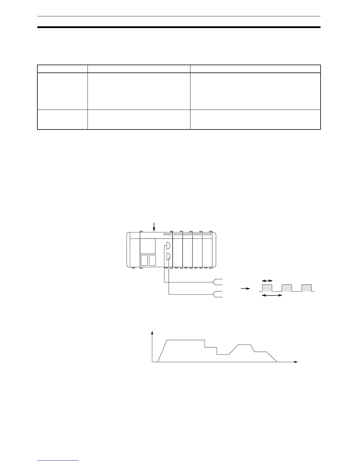
2-2-9 Fixed Duty Factor Pulse Output
The following is a description of the procedure for performing pulse outputs
from ports 1 and 2 using a duty factor of 50%.
Outline Pulse outputs from ports 1 and 2 are performed as shown in the diagram
below. Ports 1 and 2 can be used simultaneously. The pulse output of each
port can be switched to either CW (clockwise) or CCW (counterclockwise)
direction.
When outputting pulses from ports 1 and 2, the frequency can be changed in
steps or by a specified rate, as shown in the following diagram.
Pulse output from ports 1 and 2 can be performed in the following two modes:
• Continuous Mode: Pulse output continues until it is stopped by either a
SPED(64) instruction or an INI(61) instruction.
• Independent Mode: Pulse output stops automatically when a specified
number of pulses has been output. Output can also be stopped by a
SPED(64) or INI(61) instruction.
Classification Characteristics Instructions used
Ports 1 and 2 pulse
output (Fixed duty
factor)
10 Hz to 50 (20) kHz frequency.
Fixed duty factor.
Bidirectional output (CW and CCW).
Frequency can be changed smoothly.
Set number of pulses: PULS(65)
Start pulse output: SPED(64)
Change frequency: SPED(64)
Stop pulse output: SPED(64)/INI(61)
Acceleration/Deceleration at same rate: PLS2(––)
Acceleration/Deceleration at separate rates: ACC(––)
Ports 1 and 2 pulse
output (Variable
duty factor)
91.6 Hz, 1.5 kHz, or 5.9 kHz frequency.
Duty factor variable between 1% to 99%.
Unidirectional output only.
Start pulse output: PWM(––)
Stop pulse output: INI(61)
T
t
on
CPU Unit
Port 1
CW
CCW
Port 2
Frequency = 10 to 50 kHz
CW
CCW
Duty factor = = 50% (0.5)
t
on
T
Frequency
Time