12
Basic PC Operation and I/O Processes Section 1-3
1-2-5 Settings for an Analog I/O Board
The settings in DM 6611 determine the operation of an Analog I/O Board
mounted in Inner Board slot 2. (An Analog I/O Board cannot be mounted in
slot 1.)
1-3 Basic PC Operation and I/O Processes
This section explains the PC Setup settings related to basic operation and I/O
processes.
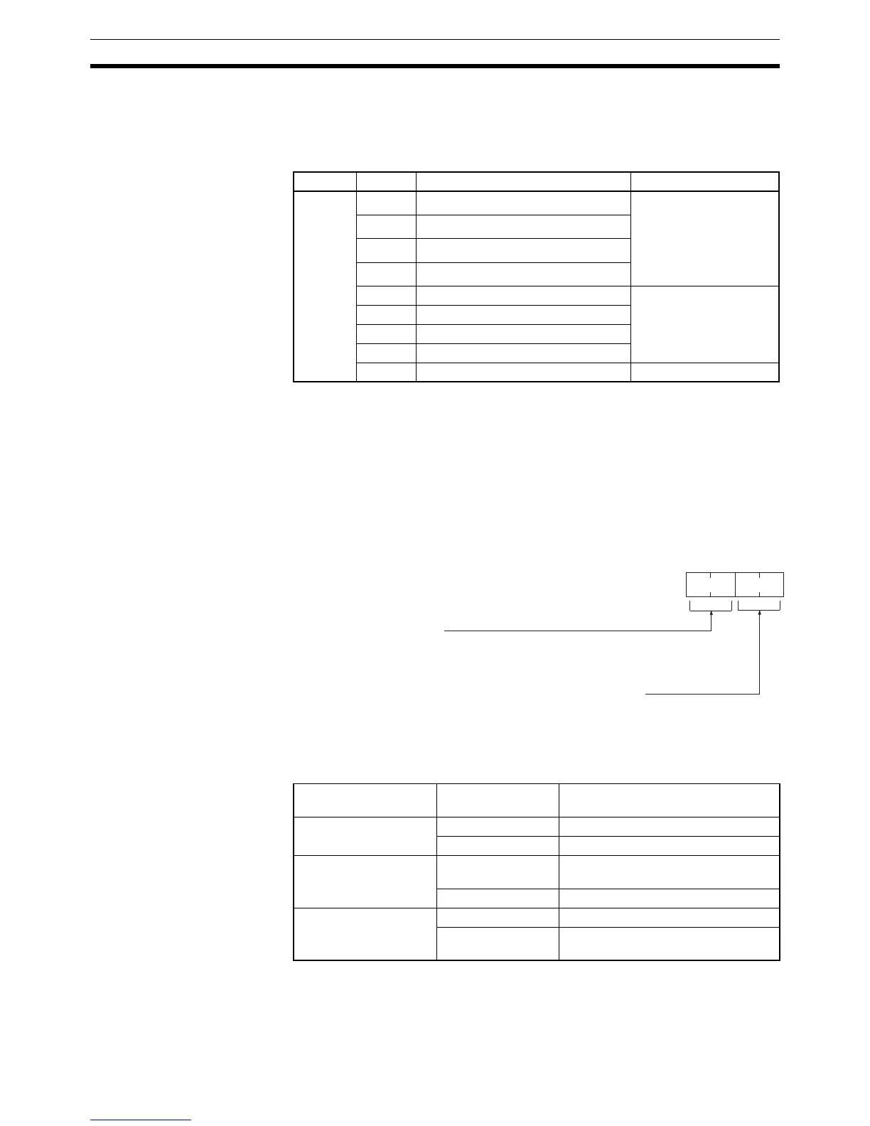
1-3-1 Startup Mode
The operating mode the PC will start in when power is turned ON can be set
as shown below.
Note 1. In these cases, the CQM1H will not be able to communicate with the con-
nected Programming Device.
Word Bits Function Settings
DM 6611 00 to 01 Analog Input 1 Input Signal Range Set the bit status of the
two bits as follows:
00: –10 to +10 V
01: 0 to 10 V
10: 0 to 5 V or
0 to 20 mA
02 to 03 Analog input 2 Input Signal Range
04 to 05 Analog input 3 Input Signal Range
06 to 07 Analog input 4 Input Signal Range
08 Analog Input 1 Usage Selection 0: Support (use) input.
1: Do not support input.
09 Analog Input 2 Usage Selection
10 Analog Input 3 Usage Selection
11 Analog Input 4 Usage Selection
12 to 15 Not used. Set to 0.
Programming Device
connected at startup
Pin 7 of the CPU
Unit’s DIP switch
Startup mode
None connected. OFF PROGRAM mode
ON RUN mode
Programming Console
connected.
OFF Operating mode set on the Program-
ming Console’s mode switch
ON PROGRAM mode (See note 1.)
Other Programming
Device connected.
OFF PROGRAM mode (See note 1.)
ON Depends upon the Connecting Cable
being used. (See note 2.)
15
Bit
DM 6600
0
Startup Mode Designation
00: Depends upon Programming Device and DIP switch settings (See table below.)
01: Operating mode last used before power was turned OFF
02: Mode set in bits 00 to 07
Startup Mode (Bits 08 to 15: Valid when bits 00 to 07 are set to 02)
00: PROGRAM mode
01: MONITOR mode
02: RUN mode
Default: Operating mode determined by Programming Device and DIP switch settings
as shown in the table below.