200
Controlling Bit Status Section 4-4
4-4 Controlling Bit Status
There are seven basic instructions that can be used generally to control indi-
vidual bit status. These are the OUTPUT, OUTPUT NOT, SET, RESET, DIF-
FERENTIATE UP, DIFFERENTIATE DOWN, and KEEP instructions. All of
these instructions appear as the last instruction in an instruction line and take
a bit address for an operand. Although details are provided in 5-9 Bit Control
Instructions, these instructions (except for OUTPUT and OUTPUT NOT,
which have already been introduced) are described here because of their
importance in most programs. Although these instructions are used to turn
ON and OFF output bits in the IR area (i.e., to send or stop output signals to
external devices), they are also used to control the status of other bits in the
IR area or in other data areas.
4-4-1 SET and RESET
The SET and RESET instructions are very similar to the OUTPUT and OUT-
PUT NOT instructions except that they only change the status of their operand
bits for ON execution conditions. Neither instructions will affect the status of its
operand bit when the execution condition is OFF.
SET will turn ON the operand bit when the execution condition goes ON, but
unlike the OUTPUT instruction, SET will not turn OFF the operand bit when
the execution condition goes OFF. RESET will turn OFF the operand bit when
the execution condition goes OFF, but unlike OUTPUT NOT, RESET will not
turn ON the operand bit when the execution condition goes OFF.
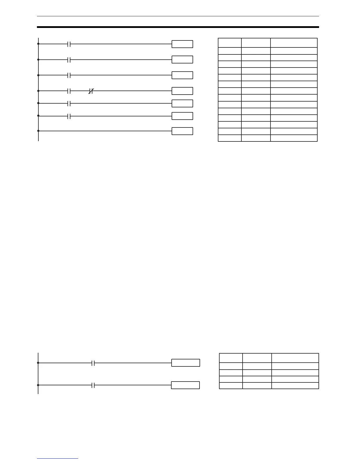
In the following example, IR 10000 will be turned ON when IR 00100 goes ON
and will remain ON until IR 00101 goes ON, regardless of the status of IR
00100. When IR 00101 goes ON, RESET will turn IR 10000 OFF.
Instruction 1
00000
Instruction 2
00001
JME(05) 00
JMP(04) 00
00004
Instruction 3
Instruction 4
00006
00005
00003
00002
JMP(04) 00
Address Instruction Operands
00000 LD 00000
00001 JMP(04) 00
00002 LD 00001
00003 Instruction 1
00004 LD 00002
00005 JMP(04) 00
00006 LD 00003
00007 AND NOT 00004
00008 Instruction 2
00009 LD 00005
00010 Instruction 3
00011 LD 00006
00012 Instruction 4
00013 JME(05) 00
00100
00101
SET 10000
RSET 10000
Address Instruction Operands
00000 LD 00100
00001 SET 10000
00002 LD 00101
00003 RSET 10000