89
Pulse I/O Board Section 2-2
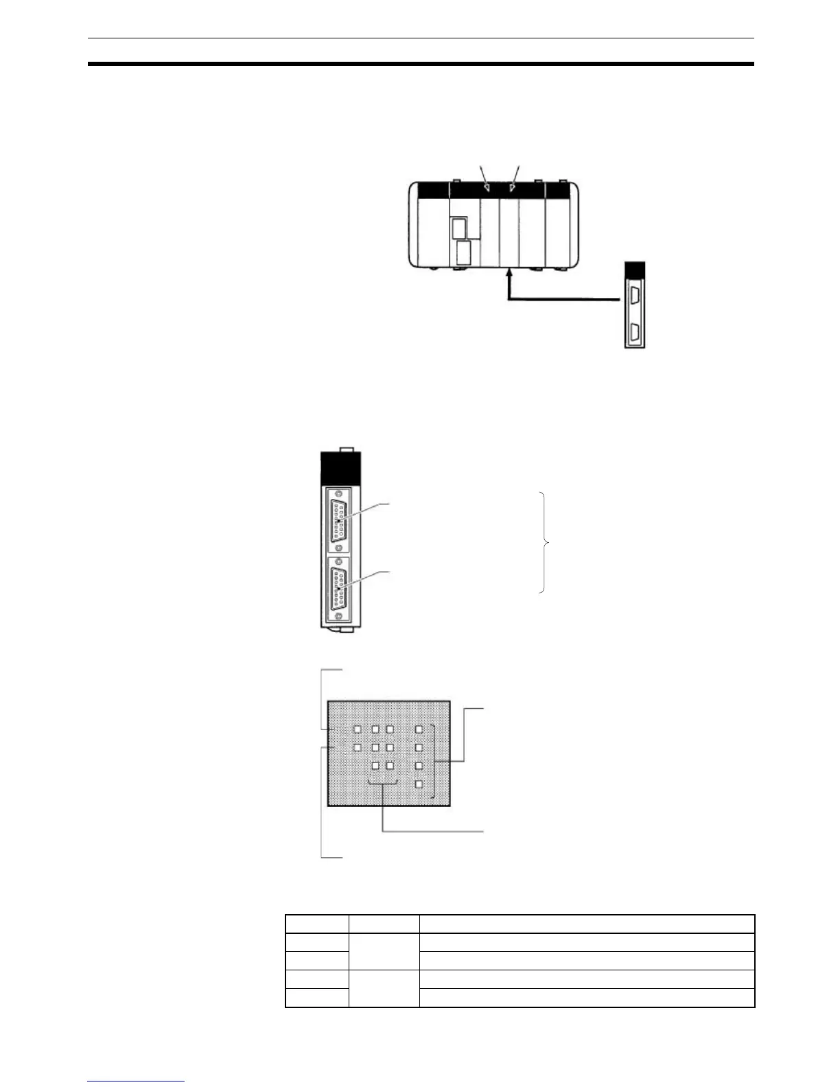
2-2-4 Applicable Inner Board Slot
The Pulse I/O Board can only be mounted in slot 2 (right slot) of the CQM1H-
CPU51/61 CPU Unit.
2-2-5 Names and Functions
The CQM1H-PLB21 Pulse I/O Board has a CN1 connector for pulse input 1
and pulse output 1, and a CN2 connector for pulse input 2 and pulse output 2.
LED Indicators
Pulse Output Indicators
Slot 1: NO Slot 2: OK
Pulse I/O Board
CQM1H-PLB21 Pulse I/O Board
CN1: Pulse input/output 1
CN2: Pulse input/output 2
Compatible connector
Socket: XM2D-1501 (OMRON)
Hood: XM2S-1511 (OMRON)
Two Sockets and two Hoods are
provided as standard with the
Pulse I/O Board.
Ready (green)
Lit when the pulse I/O functions are ready.
Error (red)
Lit when there is an error in the PC Setup settings for pulse I/O, or
when operation is interrupted during pulse output.
Pulse output (orange)
Refer to the following table.
Pulse input (orange)
Refer to the following table.
RDY
ERR
A1 A2
B1 B2
S1 S2
CW1
CCW1
CW2
CCW2
Indicator Port Function
CW1 Port 1 Lit during CW pulse output to port 1.
CCW1 Lit during CCW pulse output to port 1.
CW2 Port 2 Lit during CW pulse output to port 2.
CCW2 Lit during CCW pulse output to port 2.