124
Absolute Encoder Interface Board Section 2-3
2-3-6 Absolute Encoder Input Specifications
Instructions
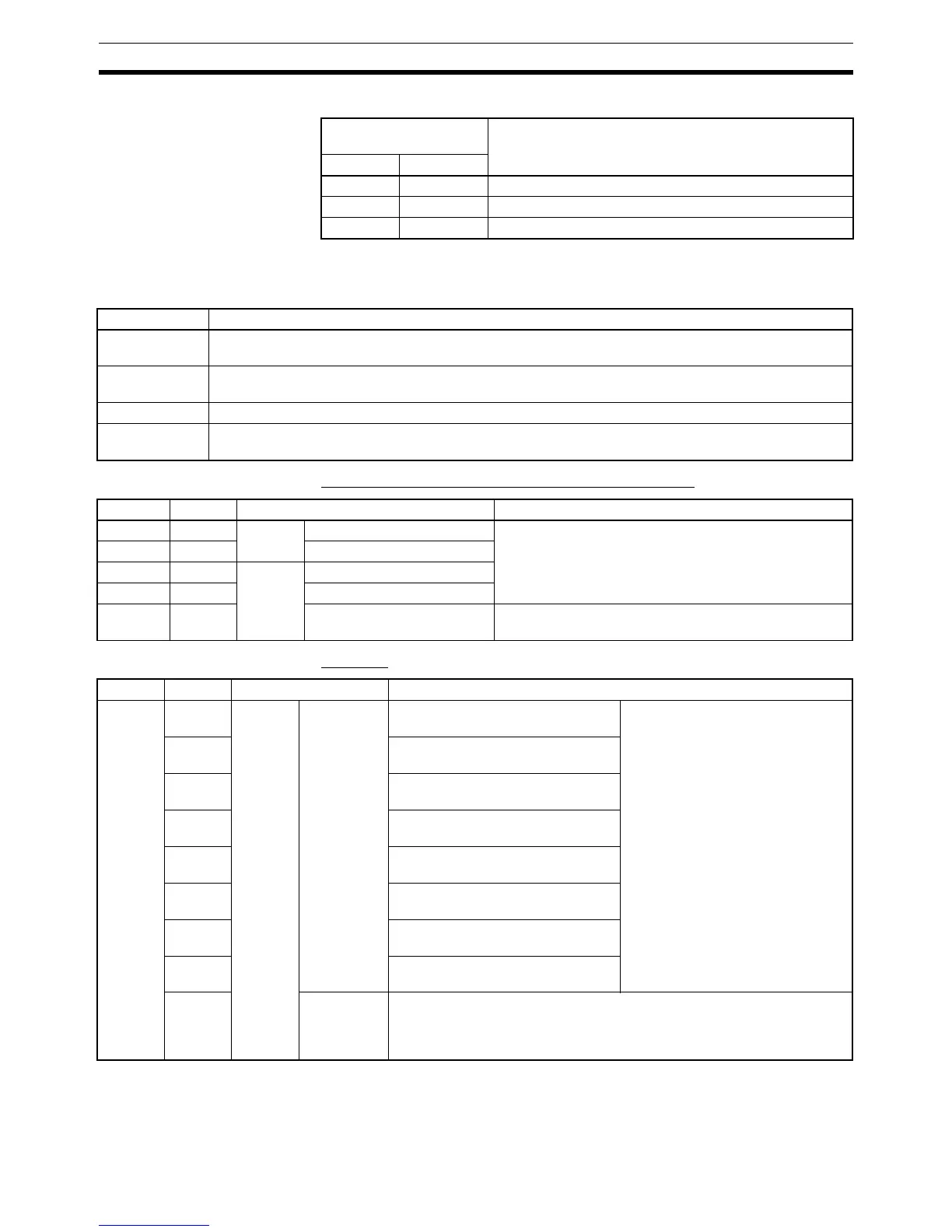
Relevant Flags and Bits Bits for Absolute Encoder Interface Board in Slot 2
AR Flags
Encoder input
indicators
Function
Port 1 Port 2
IN1 IN2 Lit when input bit 0 is ON.
INC1 INC2 Lit when value input is incremented.
DEC1 DEC2 Lit when value input is decremented.
Instruction Meaning
(@)CTBL(63) Used to register target or range comparison tables or to start comparisons for previously registered
comparison tables.
(@)INI(61) Used to start or stop comparison using registered comparison table or to change the PV of a high-
speed counter.
(@)PRV(62) Used to read the PV or status of a high-speed counter.
(@)INT(89) Used to perform mask all interrupts, such as input interrupts, interval timer interrupts, and high-speed
counter interrupts.
Word Bits Name Function
IR 232 00 to 15 Port 1 PV word (rightmost four bits) The PV of the absolute high-speed counter attached to
port 1 of the Absolute Encoder Interface Board is stored
as an 8-digit BCD after each cycle.
IR 233 00 to 15 PV word (leftmost four bits)
IR 234 00 to 15 Port 2 PV word (rightmost four bits)
IR 235 00 to 15 PV word (leftmost four bits)
IR 236 to
IR 243
00 to 15 Not used. ---
Word Bit Name Function
AR 05 00 Port 1 High-speed
Counter
Range
Comparison
Flags
ON when counter PV satisfies con-
ditions for comparison range 1
When using high-speed counter 1 in
range comparison mode, each bit
turns ON when the corresponding
condition is satisfied.
01 ON when counter PV satisfies con-
ditions for comparison range 2
02 ON when counter PV satisfies con-
ditions for comparison range 3
03 ON when counter PV satisfies con-
ditions for comparison range 4
04 ON when counter PV satisfies con-
ditions for comparison range 5
05 ON when counter PV satisfies con-
ditions for comparison range 6
06 ON when counter PV satisfies con-
ditions for comparison range 7
07 ON when counter PV satisfies con-
ditions for comparison range 8
08 High-speed
Counter
Comparison
Flag
Indicates status of comparison operation.
OFF: Stopped
ON: Comparing