EasyManua.ls Logo

Omron CQM1H - PROGRAM User Manual

Omron CQM1H - PROGRAM
602 pages
To Next Page IconTo Next Page
To Previous Page IconTo Previous Page
Page #440 background imageLoading...
Page #440 background image
415
Communications Instructions Section 5-30
Flags ER: Indirectly addressed EM/DM word is non-existent.
(Content of *EM/*DM word is not BCD, or the EM/DM area boundary
has been exceeded.)
5-30 Communications Instructions
5-30-1 RECEIVE – RXD(47)
Limitations D and D+(N÷2)–1 must be in the same data area.
DM 6144 to DM 6655 cannot be used for D or N.
N must be BCD from #0000 to #0256.
Description When the execution condition is OFF, RXD(47) is not executed. When the
execution condition is ON, RXD(47) reads N bytes of data received at the port
specified in the control word, and then writes that data in words D to
D+(N
÷2)–1. Up to 256 bytes of data can be read at one time.
If fewer than N bytes are received, the amount received will be read.
0018
0000C+2: DM 0302
15 0
@CMND(−−)
DM 0100
DM 0200
DM 0300
00000
Address Instruction Operands
00000 LD 00000
00001 AND AR 0209
00002 SEND(90)
DM 0100
DM 0200
DM 0300
AR 0209
0008
0300C+3: DM 0303
C+1: DM 0301
C: DM 0300
0003C+4: DM 0304
0064C+5: DM 0305
Bytes of command data: 0008 (8 decimal)
Bytes of response data: 0018 (24)
Transmit to the local network and the device itself
Node number 3, unit address 00 (CPU Unit)
Response requested, port number 0, 3 retries
Response monitoring time: 0064 hexadecimal (10 seconds)
8200
0A00S+2: DM 0102
15 0
0101
000AS+3: DM 0103
S+1: DM 0101
S: DM 0100
Command code: 0101 hexadecimal (MEMORY AREA READ)
Number of words to read = 0A hexadecimal (10 decimal)
DM 0010 (Data area = 82 hexadecimal, address = 000A00)
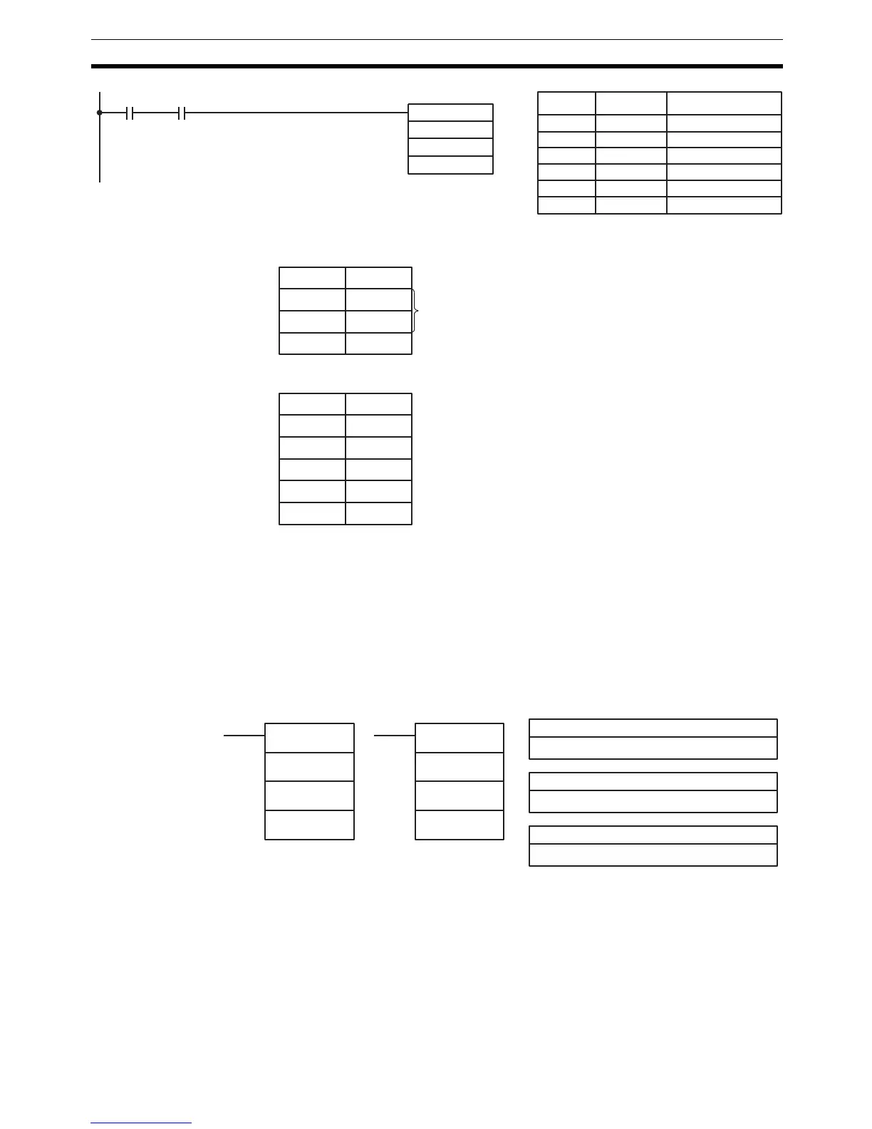
D: First destination word
IR, SR, AR, DM, EM, HR, TIM/CNT, LR
C: Control word
#
Ladder Symbols
Operand Data Areas
N: Number of bytes
IR, SR, AR, DM, EM, HR, TIM/CNT, LR, #
RXD(47)
D
C
N
@RXD(47)
D
C
N

Table of Contents

Question and Answer IconNeed help?

Do you have a question about the Omron CQM1H - PROGRAM and is the answer not in the manual?

Omron CQM1H - PROGRAM Specifications

General IconGeneral
I/O CapacityUp to 512 points
Power Supply100 to 240 VAC, 50/60 Hz or 24 VDC (depending on model)
Instruction SetBasic and advanced instructions
Operating Temperature0 to 55°C
Program Capacity7.2K to 15.2K steps
Communication PortsRS-232C
Expansion SlotsUp to 3 expansion units
TypeProgrammable Logic Controller (PLC)
CPU TypeRISC
Program Memory7.2K to 15.2K steps
I/O Points512 max
Expansion CapabilityUp to 3 expansion units
Data MemoryRAM (battery backup)

Summary

PRECAUTIONS

1 Intended Audience

Specifies the target personnel for this manual, requiring knowledge of electrical systems and FA systems.

2 General Precautions

Outlines user responsibilities for operating the product according to specifications and consulting representatives for specific applications.

3 Safety Precautions

Details critical safety warnings related to I/O refreshing, touching internal components, disassembly, and power supply handling.

5 Application Precautions

Provides essential safety guidelines for using the PC System, including grounding, power handling, and unit mounting.

SECTION 1 PC Setup and Other Features

1-1 PC Setup

Explains operating parameters for CQM1H control, including default values and how to change them.

SECTION 2 Inner Boards

2-1 High-speed Counter Board

Describes the functions, input modes, comparison operations, and external outputs of the High-speed Counter Board.

2-2 Pulse I/O Board

Details the Pulse I/O Board's support for two pulse inputs and two pulse outputs, including input modes and interrupts.

SECTION 3 Memory Areas

3-1 Memory Area Structure

Explains the memory areas used by the CQM1H PC, including IR, Work, Controller Link status, MACRO operand, Inner Board, Analog, High-speed Counter, and EM areas.

SECTION 4 Ladder-diagram Programming

4-1 Basic Procedure

Outlines the fundamental steps for writing a program, including obtaining I/O lists and drawing ladder diagrams.

4-4 Controlling Bit Status

Details instructions for controlling individual bit status: OUTPUT, OUTPUT NOT, SET, RESET, DIFFERENTIATE UP/DOWN, KEEP.

4-6 Programming Precautions

Provides essential precautions for drawing clear ladder diagrams and inputting programs, emphasizing instruction order and TR bits.

4-7 Program Execution

Describes the CPU Unit's program scan from top to bottom, checking conditions, and executing instructions.

SECTION 5 Instruction Set

SECTION 6 Host Link Commands

6-1 Host Link Command Summary

Provides a summary table of Host Link commands available for CQM1H communications.

6-4 Command and Response Formats

Details the formats for commands issued from the host computer and responses received from the PC.

6-5 Host Link Commands

Lists and describes various Host Link commands for reading and writing data in IR, SR, LR, HR, DM, EM, and AR areas.

SECTION 7 CPU Unit Operation and Processing Time

7-1 CPU Unit Operation

Explains the overall operation flowchart of the CQM1H CPU Unit and defines cycle time.

7-2 Power Interruptions

Details the CPU Unit's behavior during power interruptions and momentary power supply failures.

7-3 Cycle Time

Explains the processes involved in a single execution cycle and their respective processing times.

SECTION 8 Troubleshooting

8-2 Programming Console Operation Errors

Lists common error messages encountered when using the Programming Console and their appropriate responses.

Appendix A Programming Instructions

5-8 Ladder Diagram Instructions

Explains basic instructions like LOAD, AND, OR, and their combinations, including logic block instructions.

5-9 Bit Control Instructions

Covers instructions for controlling individual bit status: OUT, OUT NOT, SET, RESET, DIFU, DIFD, KEEP.

5-14 User Error Instructions: FAILURE ALARM AND RESET – FAL(06) and SEVERE FAILURE ALARM – FALS(07)

Describes instructions for outputting error numbers for operation, maintenance, and debugging, including non-fatal and fatal errors.

5-16 Timer and Counter Instructions

Details instructions for managing timers and counters, including TIM, TIMH, CNT, CNTR, TTIM, STIM, and CTBL.

5-29 Network Instructions

Explains instructions for communicating with other PCs via the Controller Link System, including SEND, RECV, and CMND.

5-30 Communications Instructions

Details instructions for serial communications, including RECEIVE (RXD), TRANSMIT (TXD), CHANGE SERIAL PORT SETUP (STUP), and PROTOCOL MACRO (PMCR).

Related product manuals