EasyManua.ls Logo

Omron CQM1H - PROGRAM User Manual

Omron CQM1H - PROGRAM
602 pages
To Next Page IconTo Next Page
To Previous Page IconTo Previous Page
Page #258 background imageLoading...
Page #258 background image
233
Timer and Counter Instructions Section 5-16
If IR or LR bits are used for control bits, their status will be lost during any
power interruption. If it is necessary to maintain status to resume execution at
the same step, HR bits must be used.
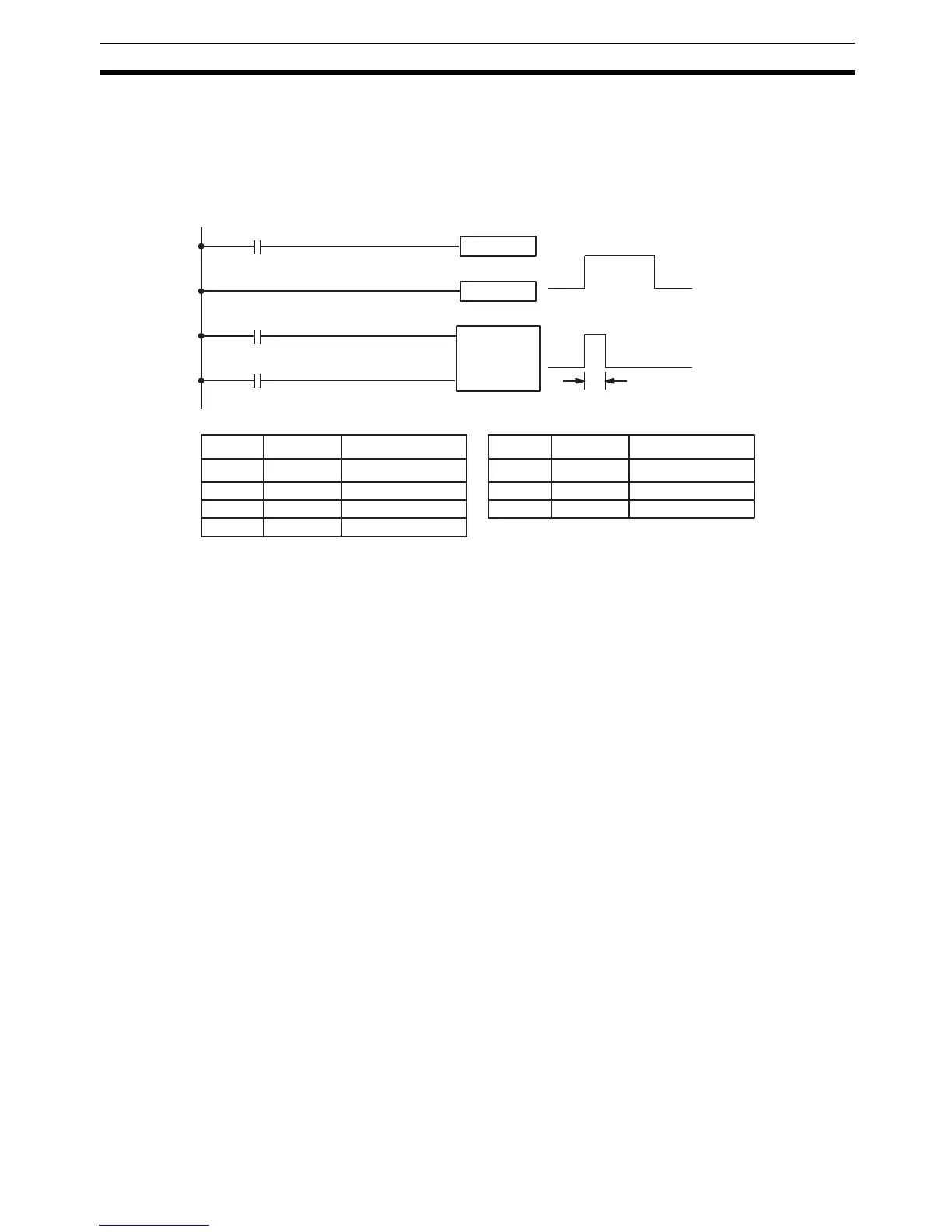
Flags 25407: Step Start Flag; turns ON for one cycle when STEP(08) is executed
and can be used to reset counters in steps as shown below if neces-
sary.
5-16 Timer and Counter Instructions
TIM and TIMH(15) are decrementing ON-delay timer instructions which
require a TIM/CNT number and a set value (SV). STIM(69) is used to control
the interval timers, which are used to activate interrupt routines.
CNT is a decrementing counter instruction and CNTR(12) is a reversible
counter instruction. Both require a TIM/CNT number and a SV. Both are also
connected to multiple instruction lines which serve as an input signal(s) and a
reset. CTBL(63), INT(89), and PRV(62) are used to manage the high-speed
counter. INT(89) is also used to stop pulse output.
Any one TIM/CNT number cannot be defined twice, i.e., once it has been
used as the definer in any of the timer or counter instructions, it cannot be
used again. Once defined, TIM/CNT numbers can be used as many times as
required as operands in instructions other than timer and counter instructions.
TIM/CNT numbers run from 000 through 511. No prefix is required when
using a TIM/CNT number as a definer in a timer or counter instruction. Once
defined as a timer, a TIM/CNT number can be prefixed with TIM for use as an
operand in certain instructions. The TIM prefix is used regardless of the timer
instruction that was used to define the timer. Once defined as a counter, a
TIM/CNT number can be prefixed with CNT for use as an operand in certain
instructions. The CNT is also used regardless of the counter instruction that
was used to define the counter.
TIM/CNT numbers can be designated as operands that require either bit or
word data. When designated as an operand that requires bit data, the TIM/
CNT number accesses a bit that functions as a `Completion Flag’ that indi-
cates when the time/count has expired, i.e., the bit, which is normally OFF, will
turn ON when the designated SV has expired. When designated as an oper-
and that requires word data, the TIM/CNT number accesses a memory loca-
tion that holds the present value (PV) of the timer or counter. The PV of a
timer or counter can thus be used as an operand in CMP(20), or any other
SNXT(09) 01000
CP
R
CNT 01
#0003
00000
00100
25407
STEP(08) 01000
1 cycle
25407
01000
Start
Address Instruction Operands Address Instruction Operands
00000 LD 00000
00001 SNXT(09) 01000
00002 STEP(08) 01000
00003 LD 00100
00004 LD 25407
00005 CNT 01
# 0003

Table of Contents

Question and Answer IconNeed help?

Do you have a question about the Omron CQM1H - PROGRAM and is the answer not in the manual?

Omron CQM1H - PROGRAM Specifications

General IconGeneral
I/O CapacityUp to 512 points
Power Supply100 to 240 VAC, 50/60 Hz or 24 VDC (depending on model)
Instruction SetBasic and advanced instructions
Operating Temperature0 to 55°C
Program Capacity7.2K to 15.2K steps
Communication PortsRS-232C
Expansion SlotsUp to 3 expansion units
TypeProgrammable Logic Controller (PLC)
CPU TypeRISC
Program Memory7.2K to 15.2K steps
I/O Points512 max
Expansion CapabilityUp to 3 expansion units
Data MemoryRAM (battery backup)

Summary

PRECAUTIONS

1 Intended Audience

Specifies the target personnel for this manual, requiring knowledge of electrical systems and FA systems.

2 General Precautions

Outlines user responsibilities for operating the product according to specifications and consulting representatives for specific applications.

3 Safety Precautions

Details critical safety warnings related to I/O refreshing, touching internal components, disassembly, and power supply handling.

5 Application Precautions

Provides essential safety guidelines for using the PC System, including grounding, power handling, and unit mounting.

SECTION 1 PC Setup and Other Features

1-1 PC Setup

Explains operating parameters for CQM1H control, including default values and how to change them.

SECTION 2 Inner Boards

2-1 High-speed Counter Board

Describes the functions, input modes, comparison operations, and external outputs of the High-speed Counter Board.

2-2 Pulse I/O Board

Details the Pulse I/O Board's support for two pulse inputs and two pulse outputs, including input modes and interrupts.

SECTION 3 Memory Areas

3-1 Memory Area Structure

Explains the memory areas used by the CQM1H PC, including IR, Work, Controller Link status, MACRO operand, Inner Board, Analog, High-speed Counter, and EM areas.

SECTION 4 Ladder-diagram Programming

4-1 Basic Procedure

Outlines the fundamental steps for writing a program, including obtaining I/O lists and drawing ladder diagrams.

4-4 Controlling Bit Status

Details instructions for controlling individual bit status: OUTPUT, OUTPUT NOT, SET, RESET, DIFFERENTIATE UP/DOWN, KEEP.

4-6 Programming Precautions

Provides essential precautions for drawing clear ladder diagrams and inputting programs, emphasizing instruction order and TR bits.

4-7 Program Execution

Describes the CPU Unit's program scan from top to bottom, checking conditions, and executing instructions.

SECTION 5 Instruction Set

SECTION 6 Host Link Commands

6-1 Host Link Command Summary

Provides a summary table of Host Link commands available for CQM1H communications.

6-4 Command and Response Formats

Details the formats for commands issued from the host computer and responses received from the PC.

6-5 Host Link Commands

Lists and describes various Host Link commands for reading and writing data in IR, SR, LR, HR, DM, EM, and AR areas.

SECTION 7 CPU Unit Operation and Processing Time

7-1 CPU Unit Operation

Explains the overall operation flowchart of the CQM1H CPU Unit and defines cycle time.

7-2 Power Interruptions

Details the CPU Unit's behavior during power interruptions and momentary power supply failures.

7-3 Cycle Time

Explains the processes involved in a single execution cycle and their respective processing times.

SECTION 8 Troubleshooting

8-2 Programming Console Operation Errors

Lists common error messages encountered when using the Programming Console and their appropriate responses.

Appendix A Programming Instructions

5-8 Ladder Diagram Instructions

Explains basic instructions like LOAD, AND, OR, and their combinations, including logic block instructions.

5-9 Bit Control Instructions

Covers instructions for controlling individual bit status: OUT, OUT NOT, SET, RESET, DIFU, DIFD, KEEP.

5-14 User Error Instructions: FAILURE ALARM AND RESET – FAL(06) and SEVERE FAILURE ALARM – FALS(07)

Describes instructions for outputting error numbers for operation, maintenance, and debugging, including non-fatal and fatal errors.

5-16 Timer and Counter Instructions

Details instructions for managing timers and counters, including TIM, TIMH, CNT, CNTR, TTIM, STIM, and CTBL.

5-29 Network Instructions

Explains instructions for communicating with other PCs via the Controller Link System, including SEND, RECV, and CMND.

5-30 Communications Instructions

Details instructions for serial communications, including RECEIVE (RXD), TRANSMIT (TXD), CHANGE SERIAL PORT SETUP (STUP), and PROTOCOL MACRO (PMCR).

Related product manuals