172
Timer/Counter Area Section 3-8
Note Because the CPM1, CPM1A, CPM2A, and SRM1(-V2) PCs have a smaller
LR area, the CQM1H’s link area setting (DM 6645) must be set to LR 00 to LR
15 when connecting 1:1 with one of these PCs.
Controller Link Data Link A Controller Link Unit can be mounted to establish a Controller Link Data Link
using automatic or manual settings. Refer to the Controller Link Unit’s Opera-
tion Manual for more details.
3-8 Timer/Counter Area
This area is used to manage timers and counters created with TIM, TIMH(15),
CNT, CNTR(12), and TTIM(––). The same numbers are used for both timers
and counters and each number can be used only once in the user program.
Do not use the same TIM/CNT number twice even for different instructions.
TIM/CNT numbers are used to create timers and counters, as well as to
access Completion Flags and present values (PVs). If a TIM/CNT number is
designated for word data, it will access the present value (PV); if it is used for
bit data, it access the Completion Flag for the timer/counter.
The Completion Flag turns ON when the PV of the timer/counter that is being
used goes to 0.
Refer to instructions beginning on page 233 for details on timers and
counters.
Ensuring TIMH(15)
Accuracy
TIM/CNT numbers 000 through 015 and interrupt processing should be used
for TIMH(15) whenever the cycle time is longer than 10 ms. Using other timer/
counter numbers or not using interrupt processing will lead to inaccuracy in
the high-speed timers. Interrupt processing can be set in DM 6629 of the PC
Setup.
Conditions Resetting TIM
and TIMH(15) PVs
The PV will be reset to the SV when program execution begins, the instruc-
tion’s input condition goes OFF, or the interlock condition goes OFF when the
instruction is in an interlocked program section (IL–ILC).
Conditions Resetting
TTIM(––) PVs
The PV will be reset to 0000 when the timer’s reset input goes ON.
The PV will be maintained when program execution begins, the instruction’s
input condition goes OFF, or the interlock condition goes OFF when the
instruction is in an interlocked program section (IL–ILC).
Conditions Resetting CNT
and CNTR(12) PVs
The PV will be reset to the SV when the counter’s reset input goes ON.
The PV will be maintained when program execution begins, the instruction’s
input condition goes OFF, or the interlock condition goes OFF when the
instruction is in an interlocked program section (IL–ILC).
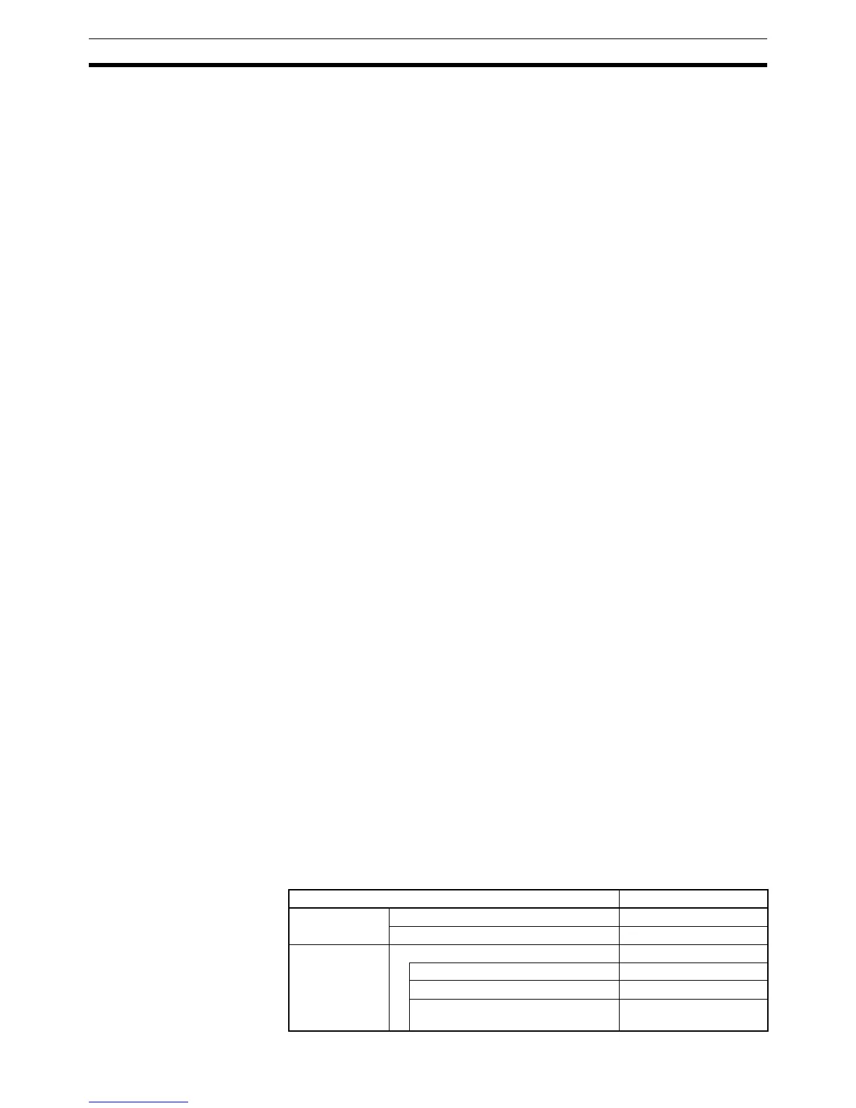
3-9 DM Area
Data is accessed in word units. As shown below, the read/write part of the DM
area can be freely read and written from the program. The rest of the DM area
is assigned specific functions in advance.
Name Range
Read/write All CQM1H CPU Units DM 0000 to DM 3071
CQM1H-CPU51/61 only DM 3072 to DM 6143
Read-only area
(see notes 1
and 2)
Entire read-only area DM 6144 to DM 6568
Controller Link DM parameters area DM 6400 to DM 6409
Routing table area DM 6450 to DM 6499
Serial Communications Board
settings
DM 6550 to DM 6559