EasyManua.ls Logo

Omron CQM1H - PROGRAM User Manual

Omron CQM1H - PROGRAM
602 pages
To Next Page IconTo Next Page
To Previous Page IconTo Previous Page
Page #239 background imageLoading...
Page #239 background image
214
Expansion Instructions Section 5-5
5-5 Expansion Instructions
A set of expansion instructions to aid in special programming needs. Function
codes can be assigned to up to 18 of the expansion instructions to enable
using them in programs. This allows the user to pick the instructions needed
by each program to more effectively use the function codes required to input
instructions.
The mnemonics of expansion instructions are followed by “(––)” as the func-
tion code to indicate that they must be assigned function codes by the user in
the instructions table before they can be used in programming (unless they
are used under their default settings).
Any of the instructions not assigned function codes will need to be assigned
function codes by the Programming Device and the CQM1H before they can
be used in programming. Changing the function codes assigned to expansion
instructions will change the meaning of instructions and operands, so be sure
to assign the function codes before programming and transfer the proper
expansion instruction settings to the CQM1H before program execution.
Example The following example shows how default function code settings can be
changed.
Function Codes for
Expansion Instructions
The following 18 function codes can be used for expansion instructions:
17, 18, 19, 47, 48, 60, 61, 62, 63, 64, 65, 66, 67, 68, 69, 87, 88, and 89
The 74 expansion instructions that can be used are listed below, along with
the default function codes that are assigned when the CQM1H is shipped.
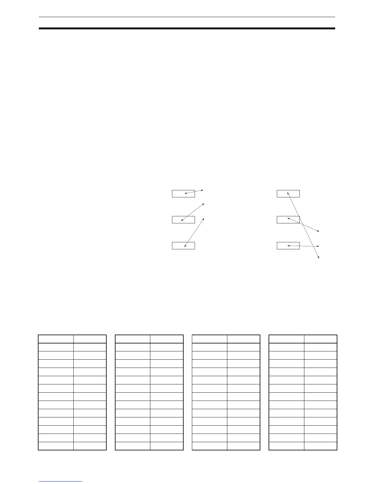
Function code 61
Function code 64
Function code 65
Function code 61
Function code 64
Function code 65
INI
SPED
PULS
MAX
MIN
SUM
INI
SPED
PULS
MAX
MIN
SUM
At the time of shipping, the function codes are
assigned as shown above. (In this example,
the instructions all relate to pulse outputs.)
If pulse outputs are not being used, and if
maximum values, minimum values, and
sums are required, then the Set Instructions
operation can be used as shown above to re-
assign instructions in the instruction table.
Mnemonic Code Mnemonic Code Mnemonic Code Mnemonic Code
ASFT 17 ACC --- FIXL --- RAD ---
TKY 18 ACOS --- FLT --- SBBL ---
MCMP 19 ADBL --- FLTL --- SCL2 ---
RXD 47 APR --- FPD --- SCL3 ---
TXD 48 ASIN --- HEX --- SEC ---
CMPL 60 ATAN --- HKY --- SIN ---
INI 61 AVG --- HMS --- SQRT ---
PRV 62 CMND --- LINE --- SRCH ---
CTBL 63 COLM --- LOG --- STUP ---
SPED 64 COS --- MAX --- SUM ---
PULS 65 CPS --- MBS --- TAN ---
SCL 66 CPSL --- MBSL --- TTIM ---
BCNT 67 DBS --- MIN --- XFRB ---

Table of Contents

Question and Answer IconNeed help?

Do you have a question about the Omron CQM1H - PROGRAM and is the answer not in the manual?

Omron CQM1H - PROGRAM Specifications

General IconGeneral
I/O CapacityUp to 512 points
Power Supply100 to 240 VAC, 50/60 Hz or 24 VDC (depending on model)
Instruction SetBasic and advanced instructions
Operating Temperature0 to 55°C
Program Capacity7.2K to 15.2K steps
Communication PortsRS-232C
Expansion SlotsUp to 3 expansion units
TypeProgrammable Logic Controller (PLC)
CPU TypeRISC
Program Memory7.2K to 15.2K steps
I/O Points512 max
Expansion CapabilityUp to 3 expansion units
Data MemoryRAM (battery backup)

Summary

PRECAUTIONS

1 Intended Audience

Specifies the target personnel for this manual, requiring knowledge of electrical systems and FA systems.

2 General Precautions

Outlines user responsibilities for operating the product according to specifications and consulting representatives for specific applications.

3 Safety Precautions

Details critical safety warnings related to I/O refreshing, touching internal components, disassembly, and power supply handling.

5 Application Precautions

Provides essential safety guidelines for using the PC System, including grounding, power handling, and unit mounting.

SECTION 1 PC Setup and Other Features

1-1 PC Setup

Explains operating parameters for CQM1H control, including default values and how to change them.

SECTION 2 Inner Boards

2-1 High-speed Counter Board

Describes the functions, input modes, comparison operations, and external outputs of the High-speed Counter Board.

2-2 Pulse I/O Board

Details the Pulse I/O Board's support for two pulse inputs and two pulse outputs, including input modes and interrupts.

SECTION 3 Memory Areas

3-1 Memory Area Structure

Explains the memory areas used by the CQM1H PC, including IR, Work, Controller Link status, MACRO operand, Inner Board, Analog, High-speed Counter, and EM areas.

SECTION 4 Ladder-diagram Programming

4-1 Basic Procedure

Outlines the fundamental steps for writing a program, including obtaining I/O lists and drawing ladder diagrams.

4-4 Controlling Bit Status

Details instructions for controlling individual bit status: OUTPUT, OUTPUT NOT, SET, RESET, DIFFERENTIATE UP/DOWN, KEEP.

4-6 Programming Precautions

Provides essential precautions for drawing clear ladder diagrams and inputting programs, emphasizing instruction order and TR bits.

4-7 Program Execution

Describes the CPU Unit's program scan from top to bottom, checking conditions, and executing instructions.

SECTION 5 Instruction Set

SECTION 6 Host Link Commands

6-1 Host Link Command Summary

Provides a summary table of Host Link commands available for CQM1H communications.

6-4 Command and Response Formats

Details the formats for commands issued from the host computer and responses received from the PC.

6-5 Host Link Commands

Lists and describes various Host Link commands for reading and writing data in IR, SR, LR, HR, DM, EM, and AR areas.

SECTION 7 CPU Unit Operation and Processing Time

7-1 CPU Unit Operation

Explains the overall operation flowchart of the CQM1H CPU Unit and defines cycle time.

7-2 Power Interruptions

Details the CPU Unit's behavior during power interruptions and momentary power supply failures.

7-3 Cycle Time

Explains the processes involved in a single execution cycle and their respective processing times.

SECTION 8 Troubleshooting

8-2 Programming Console Operation Errors

Lists common error messages encountered when using the Programming Console and their appropriate responses.

Appendix A Programming Instructions

5-8 Ladder Diagram Instructions

Explains basic instructions like LOAD, AND, OR, and their combinations, including logic block instructions.

5-9 Bit Control Instructions

Covers instructions for controlling individual bit status: OUT, OUT NOT, SET, RESET, DIFU, DIFD, KEEP.

5-14 User Error Instructions: FAILURE ALARM AND RESET – FAL(06) and SEVERE FAILURE ALARM – FALS(07)

Describes instructions for outputting error numbers for operation, maintenance, and debugging, including non-fatal and fatal errors.

5-16 Timer and Counter Instructions

Details instructions for managing timers and counters, including TIM, TIMH, CNT, CNTR, TTIM, STIM, and CTBL.

5-29 Network Instructions

Explains instructions for communicating with other PCs via the Controller Link System, including SEND, RECV, and CMND.

5-30 Communications Instructions

Details instructions for serial communications, including RECEIVE (RXD), TRANSMIT (TXD), CHANGE SERIAL PORT SETUP (STUP), and PROTOCOL MACRO (PMCR).

Related product manuals