160
SR Area Section 3-3
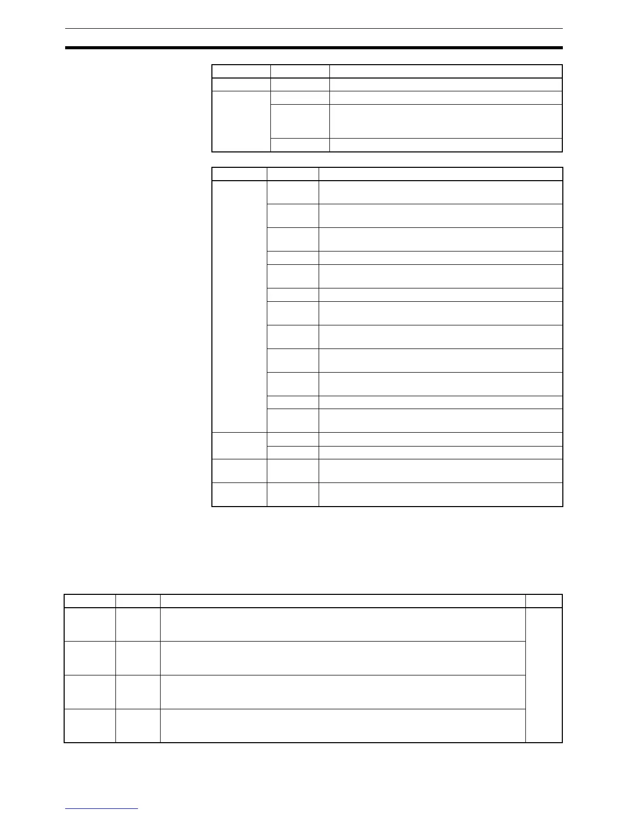
Controller Link Status
Area 2 (IR 190 to IR 195)
3-3 SR Area
These bits mainly serve as flags related to CQM1H operation. The following
table provides details on the various bit functions.
SR 244 to SR 247 can also be used as work bits when input interrupts are not
used in Counter Mode.
IR 094 00 to 15 Not used.
IR 095 00 to 10 Always 0
11 Terminator Status
0: Terminating resistance switch OFF
1: Terminating resistance switch ON
12 to 15 Always 0
Word Bits Function
Word Bits Function
IR 190 00 Network Parameters Error Flag
1: Error occurred; 0: No error
01 Data Link Table Error Flag
1: Error occurred; 0: No error
02 Routing Table Error Flag
1: Error occurred; 0: No error
03 to 06 Always 0
07 EEPROM Write Error Flag
1: Error occurred; 0: No error
08 Always 0
09 Node Number Duplication Error Flag
1: Error occurred; 0: No error
10 Network Parameters Mismatch Error Flag
1: Error occurred; 0: No error
11 Communications Controller Transmitter Error Flag
1: Error occurred; 0: No error
12 Communications Controller Hardware Error Flag
1: Error occurred; 0: No error
13 and 14 Always 0
15 Error Log Flag
1: Error record recorded; 0: No error records recorded
IR 191 00 to 07 Polling Node’s Node Number
08 to 15 Startup Node’s Node Number
IR 192 and
IR 193
00 to 15 Network Participation Status
1: Participating in network; 0: Not participating in network
IR 194 and
IR 195
00 to 15 Not used.
Word Bit(s) Function Page
SR244 00 to 15 Input Interrupt 0 Counter Mode SV
SV when input interrupt 0 is used in Counter Mode (4-digit hexadecimal, 0000 to FFFF).
(Can be used as work bits when input interrupt 0 is not used in Counter Mode.)
28
SR245 00 to 15 Input Interrupt 1 Counter Mode SV
SV when input interrupt 1 is used in Counter Mode (4-digit hexadecimal, 0000 to FFFF).
(Can be used as work bits when input interrupt 1 is not used in Counter Mode.)
SR246 00 to 15 Input Interrupt 2 Counter Mode SV
SV when input interrupt 2 is used in Counter Mode (4-digit hexadecimal, 0000 to FFFF).
(Can be used as work bits when input interrupt 2 is not used in Counter Mode.)
SR247 00 to 15 Input Interrupt 3 Counter Mode SV
SV when input interrupt 3 is used in Counter Mode (4-digit hexadecimal, 0000 to FFFF).
(Can be used as work bits when input interrupt 3 is not used in Counter Mode.)