197
Basic Ladder Diagrams Section 4-3
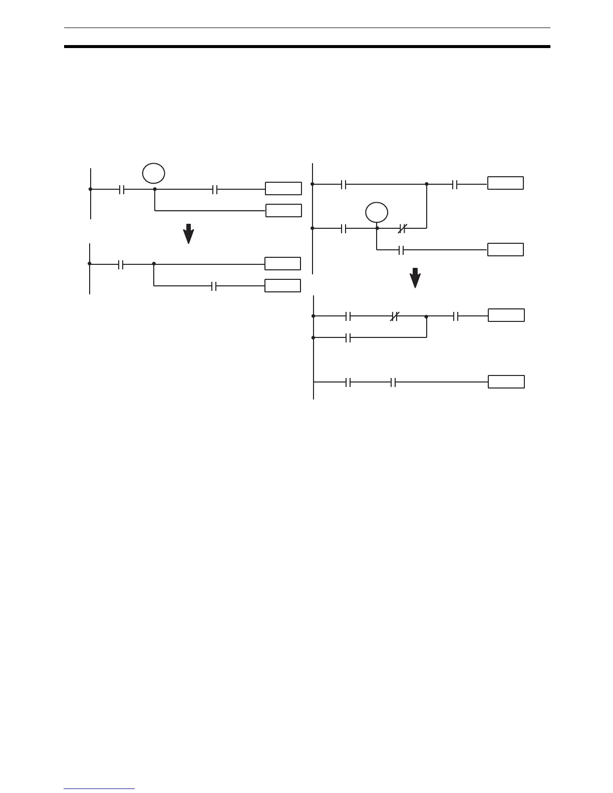
block: the bottom one, by separating the second OUTPUT instruction and
using another LOAD instruction to create the proper execution condition for it.
Note Although simplifying programs is always a concern, the order of execution of
instructions is sometimes important. For example, a MOVE instruction may be
required before the execution of a BINARY ADD instruction to place the
proper data in the required operand word. Be sure that you have considered
execution order before reorganizing a program to simplify it.
Note TR bits are must be input by the user only when programming using mne-
monic code. They are not necessary when inputting ladder diagrams directly
because they are processed for you automatically. The above limitations on
the number of branching points requiring TR bits, and considerations on
methods to reduce the number of programming instructions, still hold.
Interlocks The problem of storing execution conditions at branching points can also be
handled by using the INTERLOCK (IL(02)) and INTERLOCK CLEAR
(ILC(03)) instructions to eliminate the branching point completely while allow-
ing a specific execution condition to control a group of instructions. The
INTERLOCK and INTERLOCK CLEAR instructions are always used together.
When an INTERLOCK instruction is placed before a section of a ladder pro-
gram, the execution condition for the INTERLOCK instruction will control the
execution of all instruction up to the next INTERLOCK CLEAR instruction. If
the execution condition for the INTERLOCK instruction is OFF, all right-hand
instructions through the next INTERLOCK CLEAR instruction will be executed
with OFF execution conditions to reset the entire section of the ladder dia-
gram. The effect that this has on particular instructions is described in 5-12
INTERLOCK and INTERLOCK CLEAR – IL(02) and ILC(03).
Diagram B can also be corrected with an interlock. Here, the conditions lead-
ing up to the branching point are placed on an instruction line for the INTER-
LOCK instruction, all of lines leading from the branching point are written as
separate instruction lines, and another instruction line is added for the INTER-
LOCK CLEAR instruction. No conditions are allowed on the instruction line for
INTERLOCK CLEAR. Note that neither INTERLOCK nor INTERLOCK
CLEAR requires an operand.
Instruction 1
00000
Instruction 2
00001
TR 0
Instruction 2
00000
Instruction 1
00001
Instruction 1
00000
Instruction 2
00003
TR 0
00001
00004
00002
00001 00003
00000
00004
00002
00001
Instruction 1
Instruction 2
•