128
Absolute Encoder Interface Board Section 2-3
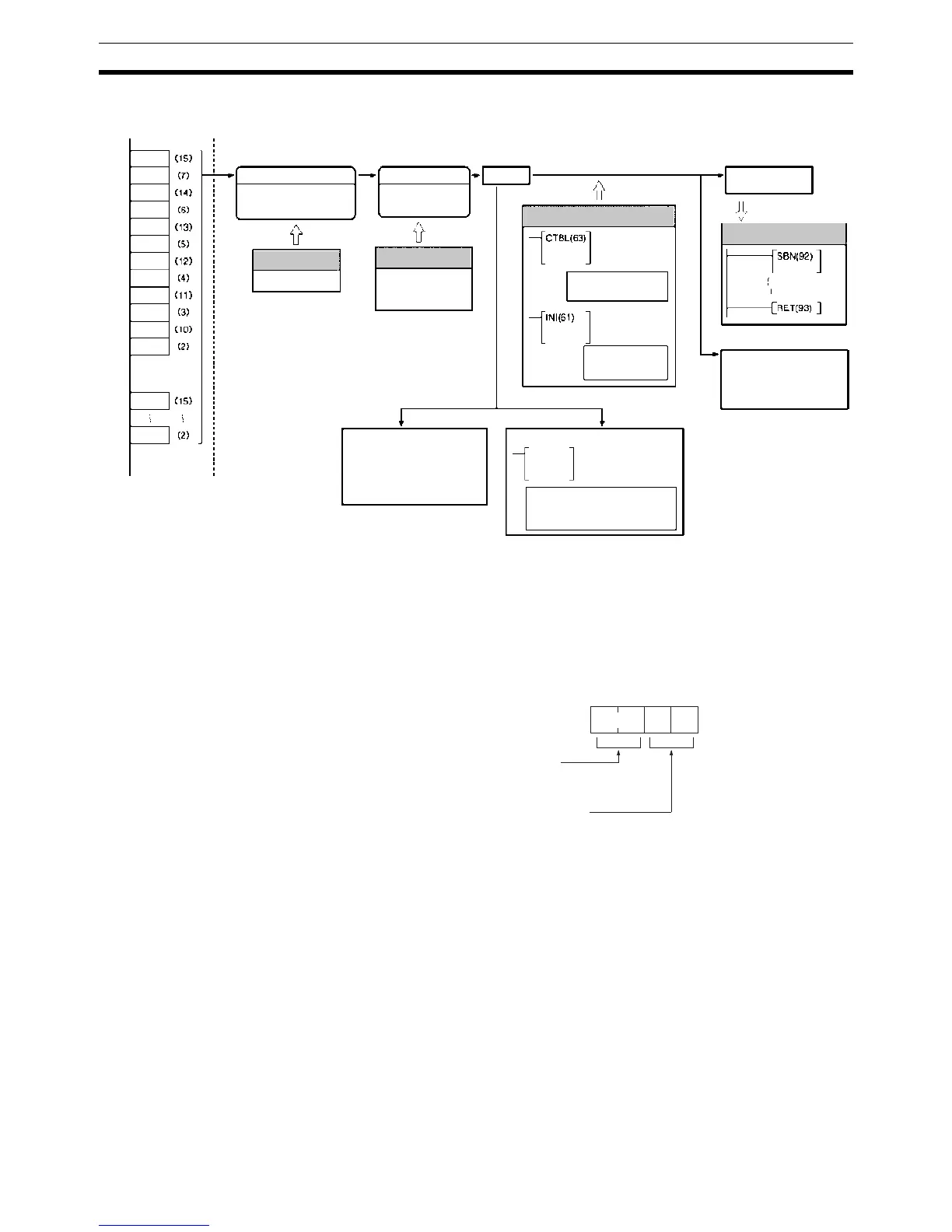
Preliminary PC Setup Make the following settings in PROGRAM mode before using absolute high-
speed counter 1 or 2 interrupts in a program.
Absolute High-speed Counter Settings
DM 6643 contains the settings for absolute high-speed counter 1, and DM
6644 contains the settings for absolute high-speed counter 2. These words
determine the operating modes and resolution settings.
High-speed Counter Function
Mode/Resolution
BCD Mode/360 Mode
8-bit, 10-bit, or 12-bit
Origin compensation
Port 1: SR 25201
Port 2: SR 25202
Count check
interrupt
Each cycle
PVs of counters
Port 1: IR 233 IR 232
Port 2: IR 235 IR 234
Each execution
PRV (62)
HIGH-SPEED
COUNTER PV
READ
PV read
Comparison operation status
read
Range comparison result read
Note: For absolute high-
speed counter interrupts.
REGISTER
COMPARISON
TABLE
Table registration
Comparison start
MODE CONTROL
PV change
Comparison
start/stop
Count
Specified subroutine
executed.
Bit 2
0
Bit 2
1
Bit 2
2
.
.
.
Bit 2
9
Bit 2
10
Bit 2
11
Range comparison result
AR 0500 to AR 0508 (Port 1)
AR 0600 to AR 0608 (Port 2)
Pin No.
Bit 2
0
.
Bit 2
11
Port 1
Port 2
PC Setup
DM 6643/DM 6644
PC Setup
Origin compensation
storage location
Port 1: DM 6611
Port 2: DM 6612
Ladder Program
Interrupt Subroutine
15 0
Bit
Operating mode:
00: BCD mode
01: 360 mode
Resolution setting:
00: 8-bit
01: 10-bit
02: 12-bit
Defaults: 0000
(BCD Mode, 8-bit resolution)
DM 6643/DM 6644