127
Absolute Encoder Interface Board Section 2-3
50° to 355°
Based on the conversions in the range 5° to 45° given above, conversions for
the remaining values are calculated as follows:
Setting (
°) ÷ 45° = A with B(°) remaining.
Conversion = (Conversion of 45
°) x A + (Conversion of B)
E.g., 145° at a resolution of 8 bits
145
° ÷ 45° = 3 with 10° remaining.
Therefore, converted value = 32 x 3 + 7 = 103
At resolutions of 10 and 12 bits, it is possible that small differences in compu-
tations may result in interrupt processing not being executed even when the
PV matches the comparison conditions.
Absolute High-speed Counter Interrupt Count
The counter’s PV can be checked using the following two methods:
• Target value method
• Range comparison method
Refer to page 36 for a description of each method.
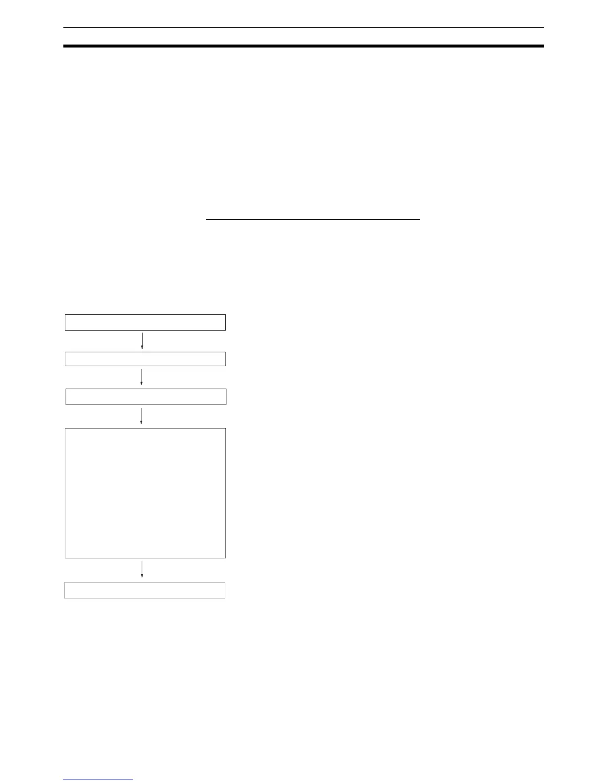
Procedure for Using Absolute High-speed Counters
Origin compensation
Set encoder to position desired as origin.
Check PV of absolute high-speed counter
1 or 2 (IR 232/IR 233 or IR 234/IR 235).
Turn ON Origin Compensation Bit for ab-
solute high-speed counter (SR 25201 or
SR 25201).
The origin compensation (4-digit BCD) will
be stored in PC Setup (DM 6611 or
DM 6612).
Verify that 0000 is stored as the PV of ab-
solute high-speed counter 1 or 2 (IR 232
or IR 234).
REGISTER COMPARISON TABLE, CTBL(63):
Port-specific comparison table registration and comparison start
MODE CONTROL, INI(61):
Port-specific PV change and comparison start
HIGH-SPEED COUNTER PV READ, PRV(62):
Port-specific high-speed counter PV read; high-speed counter com-
parison status read; range comparison result read
SUBROUTINE DEFINE, SBN(92) and RETURN, RET(93):
Creation of interrupt subroutine program (Only when using absolute
high-speed counter 1 and 2 interrupts.)
Determine operating mode and resolution.
Operating mode: BCD Mode or 360˚ Mode
Resolution: 8-bit, 10-bit, or 12-bit
Mount Board and wire inputs.
PC Setup (DM 6643/DM 6644)
Operating mode: BCD Mode or 360˚ Mode
Resolution: 8-bit, 10-bit, or 12-bit
Ladder program