78
High-speed Counter Board Section 2-1
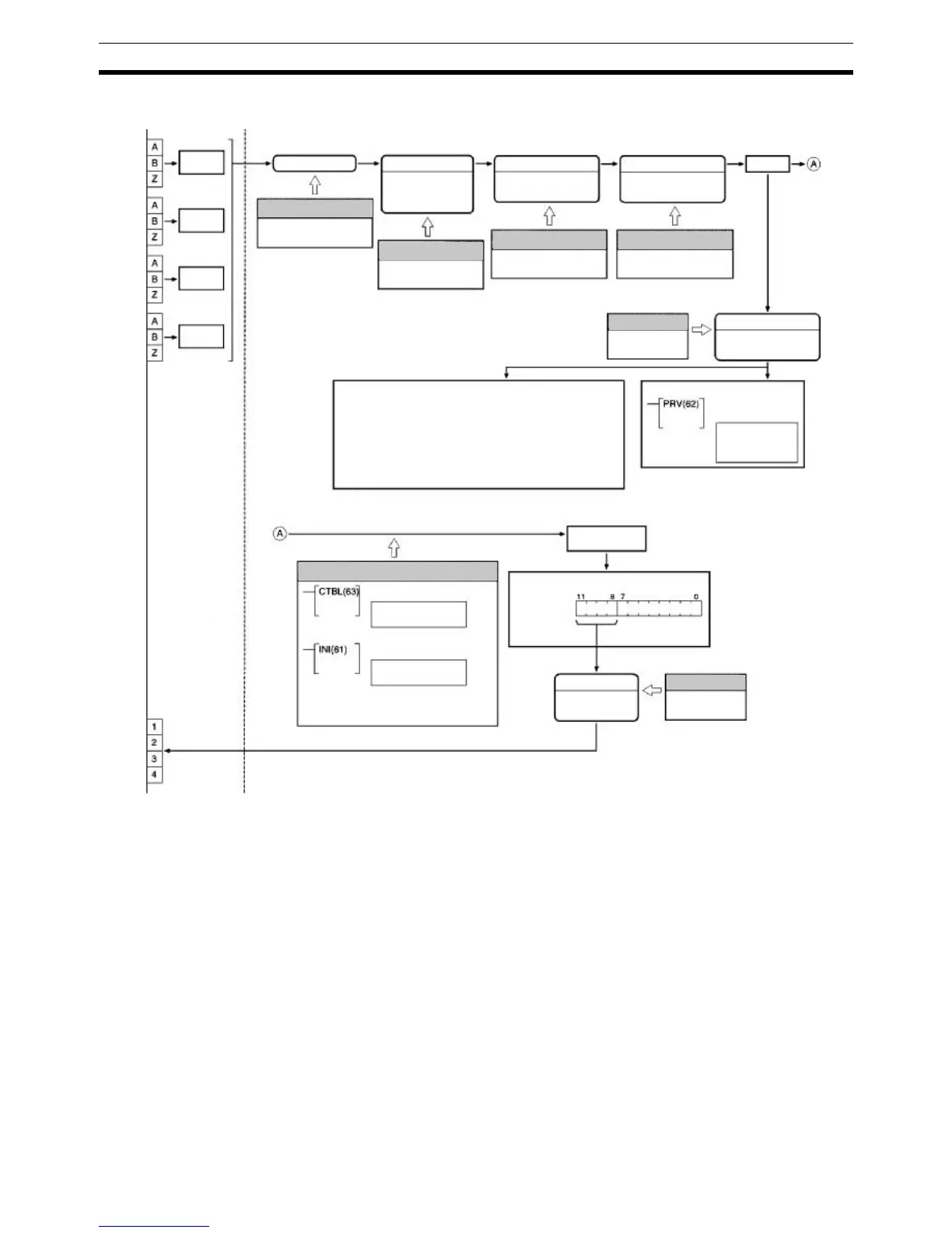
High-speed Counter Function
Input Mode
Differential phase
Up/Down pulse
Pulse/Direction
Numeric Range
Ring Mode
Linear Mode
Port 1
(CN1)
encoder
input
Port 2
(CN1)
encoder
input
Reset Method
Phase-Z + software
Software only
Count Check
(comparison)
Bits 00 to 11
of IR 208 to
IR 211 or
IR 240 to
IR 243
Each cycle
PV of Counter
Slot 2
Port 1: IR 233 and IR 232
Port 2: IR 235 and IR 234
Port 3: IR 237 and IR 236
Port 4: IR 239 and IR 238
Each execution
HIGH-SPEED COUNTER PV READ
PV
Comparison status
Table registration
Comparison start
MODE CONTROL
PV change
Comparison start/stop
Count
Input
voltage
Input
voltage
Port 1
(CN2)
encoder
input
Port 2
(CN2)
encoder
input
Input
voltage
Input
voltage
Slot 1
Port 1: IR 201 and IR 200
Port 2: IR 203 and IR 202
Port 3: IR 205 and IR 204
Port 4: IR 207 and IR 206
Data stored as 8-digit hex-
adecimal or 8-digit BCD.
Counting rate
Bit pattern stored
Flags indicated counter start/stop (IR 21212 to
IR 21215 or AR 0512 to AR 0515) and counter
comparison start/stop (IR 21308 to IR 21311 or
AR 0508 to AR 0511).
External Internal
Transistor Outputs
Sourcing/Sinking
PC Setup
Bits 04 to 07 or bits 12 to
15 of DM 6640/ DM 6641/
DM 6643/DM 6644
PC Setup
Bits 00 to 03 and 08 to 11
of DM 6640/DM 6641/
DM 6643/DM 6644
PC Setup
Bits 04 to 07 or bits 12 to
15 of DM 6640/ DM 6641/
DM 6643/DM 6644
PC Setup
Bits 04 to 07 or bits 12 to
15 of DM 6640/ DM 6641/
DM 6643/DM 6644
PC Setup
Bits 00 to 03 of
DM 6611
PC Setup
Bits 08 to 11 of
DM 6602/DM 6611
Ladder Program
REGISTER COMPARISON TABLE