94
Pulse I/O Board Section 2-2
Relevant Flags and
Control Bits (for Pulse
Output)
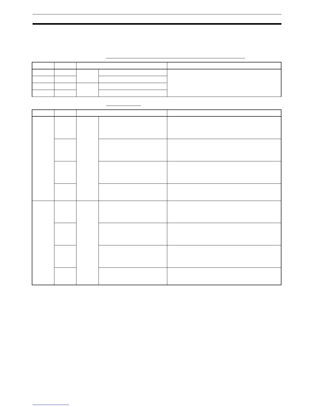
Bits for Slot 2 of Inner Board when Using Pulse I/O Board
AR Area Flags
Word Bits Name Function
IR 236 00 to 15 Port 1 PV word (rightmost four digits) The PV of the pulse output associated with each port
of the Pulse I/O Board is stored as an 8-digit BCD after
each cycle.
When pulse output is not used, these bits can be used
as internal auxiliary bits.
IR 237 00 to 15 PV word (leftmost four digits)
IR 238 00 to 15 Port 2 PV word (rightmost four digits)
IR 239 00 to 15 PV word (leftmost four digits)
Word Bit Name Function
AR 05 12 Port 1
Pulse
Output
Flags
Deceleration Specified Flag Indicates passage through deceleration point when
deceleration is specified.
0: Not specified
1: Specified
13 Number of Pulses Specified
Flag
Indicates whether or not the number of pulses has
been set using PULS(65).
0: Not specified
1: Specified
14 Pulse Output Completed Flag Indicates completion of the pulse output by SPED(64),
PLS2(––), or ACC(––).
0: Not completed
1: Completed
15 Pulse Output In Progress Flag Indicates the execution status of the pulse output.
0: No pulse output
1: Pulse output in progress
AR 06 12 Port 2
Pulse
Output
Flags
Deceleration Specified Flag Indicates passage through deceleration point when
deceleration is specified.
0: Not specified
1: Specified
13 Number of Pulses Specified
Flag
Indicates whether or not the number of pulses has
been set using PULS(65).
0: Not specified
1: Specified
14 Pulse Output Completed Flag Indicates completion of the pulse output by
SPED(64), PLS2(––), or ACC(––).
0: Not completed
1: Completed
15 Pulse Output In Progress Flag Indicates the execution status of the pulse output.
0: No pulse output
1: Pulse output in progress