97
Pulse I/O Board Section 2-2
the count falls below the lower limit an underflow is generated, and if it ex-
ceeds the upper limit an overflow is generated. The PV will remain at
0838 8607 for overflows and F838 8608 for underflows, counting or com-
parison will be stopped (and the comparison table retained), and AR 0509
(port 1) or AR 0609 (port 2) will be turned ON.
One of the methods in the following section should be used to reset the
counter when restarting the counting operation. The counter will be reset
automatically when program execution is started or stopped.
Note The following signal transitions are handled as forward (incrementing) pulses:
Phase-A leading edge
→ phase-B leading edge → phase-A trailing edge →
phase-B trailing edge.
The following signal transitions are handled as reverse (decrementing) pulses:
Phase-B leading edge
→ phase-A leading edge → phase-B trailing edge →
phase-A trailing edge.
Reset Methods The following two methods can be used to determine the timing by which the
PV of the counter is reset (i.e., set to 0):
• Phase-Z signal + software reset
• Software reset
Either the phase-Z signal + software reset or software reset alone may be
used to reset the PV of the count. These resets operate in the same way as
for high-speed counter 0 (the built-in high-speed counter). Refer to page 35
for details. The Reset Bits of high-speed counters 1 and 2 are as follows:
Reset Bit of high-speed counter 1: SR 25201
Reset Bit of high-speed counter 2: SR 25202
Note 1. Since the reset bits for high-speed counters 1 and 2 (SR 25201 and SR
25202) are refreshed during each cycle, a flag must be ON for a minimum
of 1 full cycle to be read reliably.
2. Even after a reset, the comparison table registration status, comparison
execution status, and range comparison results are retained unchanged.
(If a comparison was being executed before the reset, it will continue.)
Count Check Methods for
High-speed Counter
Interrupts
Just as for high-speed counter 0, the following two count check methods can
be used for high-speed counters 1 and 2:
• Target value method
• Range comparison method
Refer to page 36 for a description of each method.
For the target value method, up to 48 conditions can be registered in the com-
parison table. When the PV of the counter matches one of the 48 registered
comparison values, the corresponding interrupt subroutine will be executed.
For the range comparison method, 8 comparison conditions are always regis-
tered in the comparison table. When the PV of the counter lies within the
upper and lower limits for one of the ranges 1 to 8, the corresponding interrupt
subroutine will be executed.
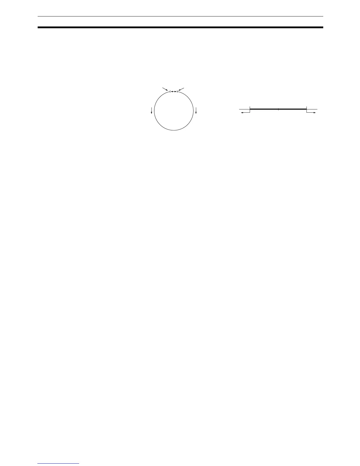
Ring Mode
0
Max. count value
Decrement Increment
Linear Mode
0−8.388,608 8.388,607
Underflow Overflow