EasyManua.ls Logo

Omron CQM1H - PROGRAM User Manual

Omron CQM1H - PROGRAM
602 pages
To Next Page IconTo Next Page
To Previous Page IconTo Previous Page
Page #126 background imageLoading...
Page #126 background image
101
Pulse I/O Board Section 2-2
Starting and Stopping Comparison
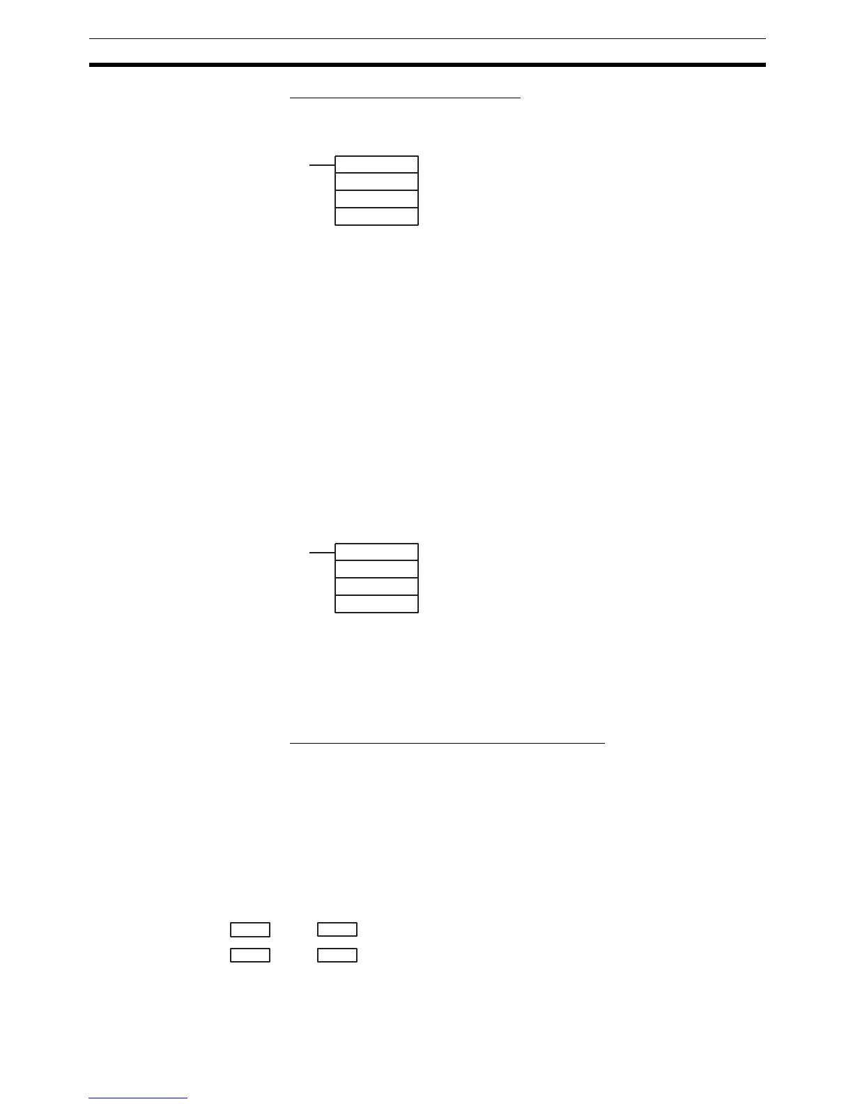
1,2,3... 1. Use CTBL(63) to save the comparison table in the CQM1H and begin com-
parisons.
If C is set to 000, then comparisons will be made using the target value
method; if 001, they will be made using the range comparison method. In
both cases the comparisons will begin after the comparison table is regis-
tered. While comparisons are being performed, high-speed counter 1 and
2 interrupts will be executed according to the comparison table. Refer to
the explanation of CTBL(63) in SECTION 5 Instruction Set for details on
the contents of the comparison tables that are saved.
Note Although setting the value of C to 002 registers a target value com-
parison table, and setting C to 003 registers a range comparison ta-
ble, comparison does not start automatically. In these cases, INI(61)
must be used to start the comparison operation.
2. To stop comparisons, execute INI(61) as shown below. Specify port 1 or 2
in P (P=001 or 002).
Note 1. To restart comparisons, set the first operand to the port number, and the
second operand to “000” (execute comparison), and execute the INI(61) in-
struction.
2. A table that has been registered will be retained in the CQM1H during op-
eration (i.e., during program execution) until a new table is registered.
Reading the PV of High-speed Counters 1 and 2
The following two methods can be used to read the PVs of high-speed
counters 1 and 2:
Reading the PV from memory
Using PRV(62)
Reading the PV from Memory
The PVs of high-speed counters 1 and 4 are stored in the corresponding data
area words in the following way.
Note These words are refreshed only once every cycle, so they may differ from the
actual PV.
(@)CTBL(63)
P
C
TB
P: Port
001: Port 1
002: Port 2
C: Mode
000: Target value table registered and comparison begun
001: Range table registered and comparison begun
002: Target table registered only
003: Range table registered only
TB: Beginning word of comparison table
(@)INI(61)
P
001
000
P: Port
001: Port 1
002: Port 2
Leftmost four digits Rightmost four digits Linear Mode Ring Mode
IR 233
IR 232 F8388608 to 08388607
(8,388,608 to 8,388,607)
(The leftmost digit becomes F when the number is
negative.)
00000000 to 00064999Port 1:
IR 235 IR 234
Port 2:

Table of Contents

Question and Answer IconNeed help?

Do you have a question about the Omron CQM1H - PROGRAM and is the answer not in the manual?

Omron CQM1H - PROGRAM Specifications

General IconGeneral
I/O CapacityUp to 512 points
Power Supply100 to 240 VAC, 50/60 Hz or 24 VDC (depending on model)
Instruction SetBasic and advanced instructions
Operating Temperature0 to 55°C
Program Capacity7.2K to 15.2K steps
Communication PortsRS-232C
Expansion SlotsUp to 3 expansion units
TypeProgrammable Logic Controller (PLC)
CPU TypeRISC
Program Memory7.2K to 15.2K steps
I/O Points512 max
Expansion CapabilityUp to 3 expansion units
Data MemoryRAM (battery backup)

Summary

PRECAUTIONS

1 Intended Audience

Specifies the target personnel for this manual, requiring knowledge of electrical systems and FA systems.

2 General Precautions

Outlines user responsibilities for operating the product according to specifications and consulting representatives for specific applications.

3 Safety Precautions

Details critical safety warnings related to I/O refreshing, touching internal components, disassembly, and power supply handling.

5 Application Precautions

Provides essential safety guidelines for using the PC System, including grounding, power handling, and unit mounting.

SECTION 1 PC Setup and Other Features

1-1 PC Setup

Explains operating parameters for CQM1H control, including default values and how to change them.

SECTION 2 Inner Boards

2-1 High-speed Counter Board

Describes the functions, input modes, comparison operations, and external outputs of the High-speed Counter Board.

2-2 Pulse I/O Board

Details the Pulse I/O Board's support for two pulse inputs and two pulse outputs, including input modes and interrupts.

SECTION 3 Memory Areas

3-1 Memory Area Structure

Explains the memory areas used by the CQM1H PC, including IR, Work, Controller Link status, MACRO operand, Inner Board, Analog, High-speed Counter, and EM areas.

SECTION 4 Ladder-diagram Programming

4-1 Basic Procedure

Outlines the fundamental steps for writing a program, including obtaining I/O lists and drawing ladder diagrams.

4-4 Controlling Bit Status

Details instructions for controlling individual bit status: OUTPUT, OUTPUT NOT, SET, RESET, DIFFERENTIATE UP/DOWN, KEEP.

4-6 Programming Precautions

Provides essential precautions for drawing clear ladder diagrams and inputting programs, emphasizing instruction order and TR bits.

4-7 Program Execution

Describes the CPU Unit's program scan from top to bottom, checking conditions, and executing instructions.

SECTION 5 Instruction Set

SECTION 6 Host Link Commands

6-1 Host Link Command Summary

Provides a summary table of Host Link commands available for CQM1H communications.

6-4 Command and Response Formats

Details the formats for commands issued from the host computer and responses received from the PC.

6-5 Host Link Commands

Lists and describes various Host Link commands for reading and writing data in IR, SR, LR, HR, DM, EM, and AR areas.

SECTION 7 CPU Unit Operation and Processing Time

7-1 CPU Unit Operation

Explains the overall operation flowchart of the CQM1H CPU Unit and defines cycle time.

7-2 Power Interruptions

Details the CPU Unit's behavior during power interruptions and momentary power supply failures.

7-3 Cycle Time

Explains the processes involved in a single execution cycle and their respective processing times.

SECTION 8 Troubleshooting

8-2 Programming Console Operation Errors

Lists common error messages encountered when using the Programming Console and their appropriate responses.

Appendix A Programming Instructions

5-8 Ladder Diagram Instructions

Explains basic instructions like LOAD, AND, OR, and their combinations, including logic block instructions.

5-9 Bit Control Instructions

Covers instructions for controlling individual bit status: OUT, OUT NOT, SET, RESET, DIFU, DIFD, KEEP.

5-14 User Error Instructions: FAILURE ALARM AND RESET – FAL(06) and SEVERE FAILURE ALARM – FALS(07)

Describes instructions for outputting error numbers for operation, maintenance, and debugging, including non-fatal and fatal errors.

5-16 Timer and Counter Instructions

Details instructions for managing timers and counters, including TIM, TIMH, CNT, CNTR, TTIM, STIM, and CTBL.

5-29 Network Instructions

Explains instructions for communicating with other PCs via the Controller Link System, including SEND, RECV, and CMND.

5-30 Communications Instructions

Details instructions for serial communications, including RECEIVE (RXD), TRANSMIT (TXD), CHANGE SERIAL PORT SETUP (STUP), and PROTOCOL MACRO (PMCR).

Related product manuals