150
IR Area Section 3-2
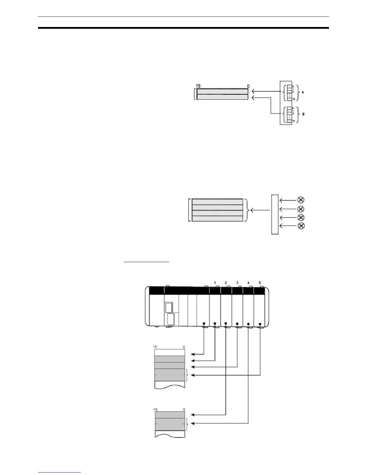
32-point I/O Units Two input words are allocated to each 32-point Input Unit and two output
words are allocated to each 32-point Output Unit. I/O points 0 to 15 of connec-
tor pin A correspond to bits 00 to 15 of the first allocated word (n) and I/O
points 0 to 15 of connector pin B correspond to bits 00 to 15 of the next allo-
cated word (n+1).
Dedicated I/O Units Dedicated I/O Units require a predetermined number of input bits, output bits,
or both input and output bits. In some Dedicated I/O Units, the number of
words required may depend on the Unit’s DIP switch settings.
For example, a CQM1-AD041 Analog Input Unit requires either 4 input words
or 2 input words. (The Analog Input Unit requires 4 input words when 4 analog
inputs are being used and 2 input words when 2 analog inputs are being
used.)
Input words and output words that were not allocated to Units can be used as
work words.
I/O Allocation Example CPU Block Only
This example shows the I/O allocation for a PC with two DC Input Units, two
Transistor Output Units, and a Sensor Unit.
Two words allocated
32-point Units
Analog inputs
Four words allocated
IR 000
IR 001
IR 002
IR 003
IR 004
IR 100
IR 101
IR 102
I
N
16
O
U
T
16
I
N
8
O
U
T
32
S
E
N
IN: Input Unit
OUT: Output Unit
SEN: Sensor Unit
Input area
Output area
16 outputs
32 outputs
Sensor Unit
(CPU Unit inputs)
16 inputs
8 inputs