156
IR Area Section 3-2
Note Applicable only for CQM1H-SCB41, lot numbers 0320 or later.
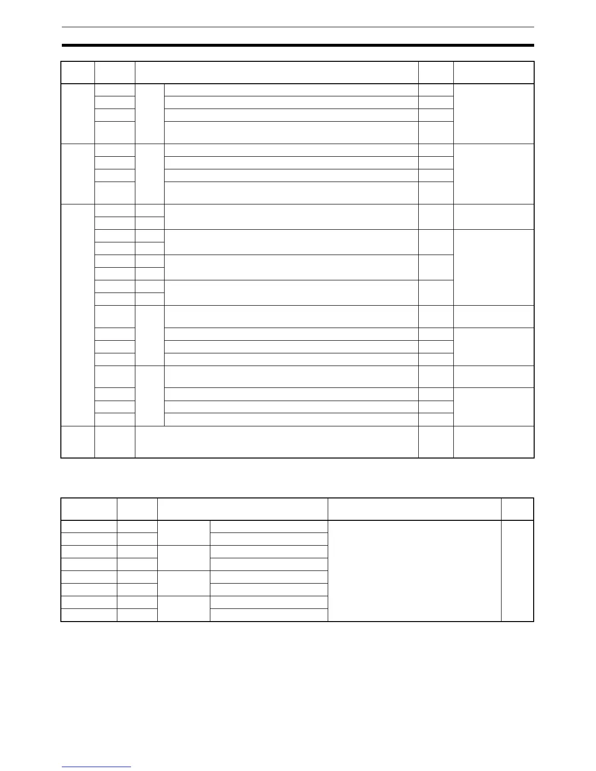
High-speed Counter Board Flags/Bits
IR 205 00 to 03 Port 1 Completed Reception Case Number RProtocol macro
04 to 07 Completed Step Number R
08 to 14 Not used. R
15 IR 20408 to IR 20411 Data Stored Flag
0: No data stored; 1: Data stored
R
IR 206 00 to 03 Port 2 Completed Reception Case Number RProtocol macro
04 to 07 Completed Step Number R
08 to 14 Not used. R
15 IR 20412 to IR 20415 Data Stored Flag
0: No data stored; 1: Data stored
R
IR 207 00 Port 1 Serial Communications Port Restart Bits W All modes
01 Port 2
02 Port 1 Continuous Trace Start/Stop Bits WProtocol macro
03 Port 2
04 Port 1 Shot Trace Start/Stop Bits W
05 Port 2
06 Port 1 Echoback Disable Bit (Only used for modem control in protocol
macro mode. See note.)
W
07 Port 2
08 Port 1 Protocol Macro Executing Flag R No-protocol or
Protocol macro
09 Step Error Processing Flag RProtocol macro
10 Sequence End Completion Flag R
11 Forced Abort Bit W
12 Port 2 Protocol Macro Executing Flag R No-protocol or
Protocol macro
13 Step Error Processing Flag RProtocol macro
14 Sequence End Completion Flag R
15 Forced Abort Bit W
IR 208
to
IR 215
00 to 15 Not used. --- ---
Word Bits Name Function Read/
Write
IR 200 00 to 15 High-speed
Counter 1
PV (rightmost 4 digits) Contains the high-speed counter PV for
each of the High-speed Counter Board’s
ports.
Note The PV data format (BCD or hexa-
decimal) can be set in the PC Setup
(DM 6602.)
R
IR 201 00 to 15 PV (leftmost 4 digits)
IR 202 00 to 15 High-speed
Counter 2
PV (rightmost 4 digits)
IR 203 00 to 15 PV (leftmost 4 digits)
IR 204 00 to 15 High-speed
Counter 3
PV (rightmost 4 digits)
IR 205 00 to 15 PV (leftmost 4 digits)
IR 206 00 to 15 High-speed
Counter 4
PV (rightmost 4 digits)
IR 207 00 to 15 PV (leftmost 4 digits)
Word Bits Function Read/
Write
Communications
modes