248
Timer and Counter Instructions Section 5-16
For higher values, find the converted value to the nearest 45° and add the
remainder from the table. For example, to convert 145
° into 8-bit resolution:
32
×3 (for 135°) + 7 (for 10°) = 103.
!Caution With 10-bit and 12-bit resolution, interrupt processing might not be triggered
when the angular value matches the comparison value because the con-
verted values do not match exactly.
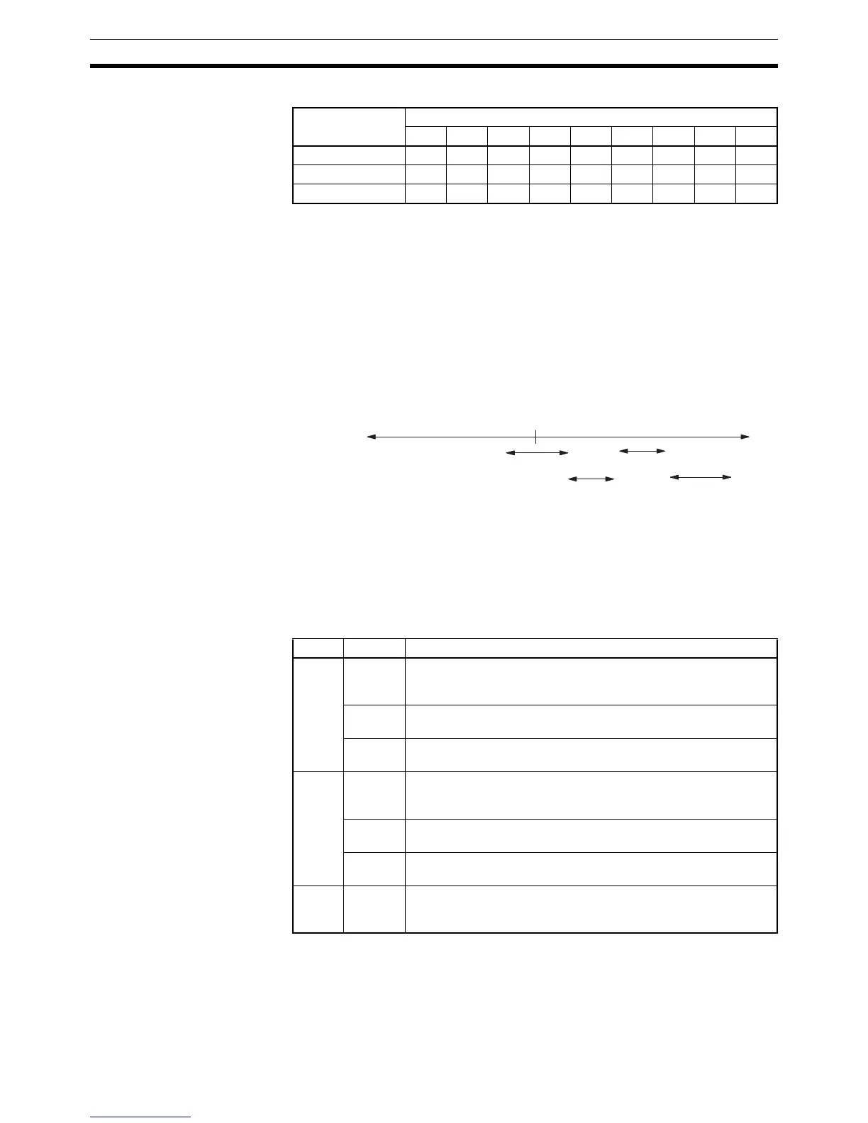
Range Comparison Operation
The following diagram illustrates the operation of range comparisons for range
settings 1 through 4 set consecutively in the comparison table.
As illustrated above, the current count is compared against all the comparison
ranges at the same time and the result for each range is output.
AR Area Flags
The following AR area flags indicate the status of comparison operations for
high-speed counter 0 in the CPU Unit and high-speed counters 1 and 2 in the
Pulse I/O Board or Absolute Encoder Interface Board.
Operation with the
High-speed Counter
Board
When the execution condition is OFF, CTBL(63) is not executed. When the
execution condition is ON, CTBL(63) registers a comparison table for use with
the high-speed counter PV. Depending on the value of C, comparison with the
high-speed counter PV can begin immediately or it can be started separately
with INI(61).
Resolution Converted value
5° 10° 15° 20° 25° 30° 35° 40° 45°
8-bit (0 to 255) 4 7 11 14 18 21 25 28 32
10-bit (0 to 1023) 14 28 43 57 71 85 100 114 128
12-bit (0 to 4095) 57 114 171 228 284 341 398 455 512
Word Bit(s) Operation
AR 05 00 to 07 High-speed Counter 1 (Port 1) Range Comparison Flags
Bits 00 to 07 will be turned ON when the counter PV is within the
corresponding range (1 to 8).
08 High-speed Counter 1 (Port 1) Comparison Flag
This flag will be ON during PV comparison.
09 High-speed Counter 1 (Port 1) Overflow/Underflow Flag
This flag will be ON when an overflow or underflow occurred.
AR 06 00 to 07 High-speed Counter 2 (Port 2) Range Comparison Flags
Bits 00 to 07 will be turned ON when the counter PV is within the
corresponding range (1 to 8).
08 High-speed Counter 2 (Port 2) Comparison Flag
This flag will be ON during PV comparison.
09 High-speed Counter 2 (Port 2) Overflow/Underflow Flag
This flag will be ON when an overflow or underflow occurred.
AR 11 00 to 07 High-speed Counter 0 Range Comparison Flags
Bits 00 to 07 will be turned ON when the counter PV is within the
corresponding range (1 to 8).
Count
Range
1
0
Range
4
Range
3
Range
2