254
Timer and Counter Instructions Section 5-16
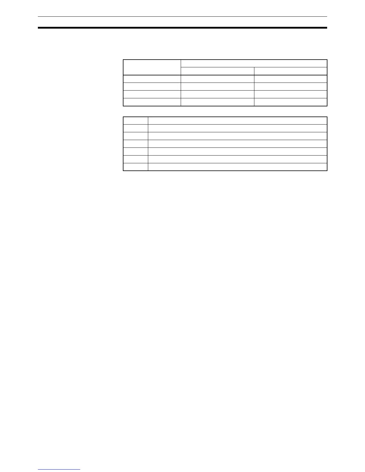
When the High-speed Counter Board is installed in slot 1, the bit patterns are
output to IR 208 through IR 211. When the Board is installed in slot 2, the bit
patterns are output to IR 240 through IR 243.
The following table shows the function of the bits in the allocated IR word.
Note 1. When using target comparison for high-speed counters 1 to 4, set the tar-
get values so that bit patterns are output at an interval of 0.2 ms or greater.
2. When using range comparison for high-speed counters 1 to 4, set the limits
so that the PV of the counter remains between the upper and lower limit for
0.5 ms or greater. (Upper limit – Lower limit > 0.0005 x Input frequency)
3. When using target comparison for high-speed counters 1 to 4, it does not
matter if the target value is reach by incrementing or decrementing. This is
also true for target value comparison for the High-speed Counter Board,
but is different from high-speed counters 1 and 2 in Ring Mode on the
Pulse I/O Board or high-speed counters 1 and 2 on the Absolute Encoder
Interface Board.
High-speed counters 1 to 4 begin counting from 0 when CQM1H program
operation begins, but the bit pattern will not be output until comparison
begins. Use INI(61) to stop comparison.
A comparison table registered with CTBL(63) is valid until CQM1H program
operation ends or a different comparison table is registered. The cycle time
can be reduced by executing a differentiated variation of CTBL(63) when
required.
Flags ER: The specified port and function are not compatible.
There is another CTBL(63) instruction with a different comparison
method in the subroutine called by CTBL(63) instruction.
A CTBL(63) instruction with a different comparison method is exe-
cuted during comparison.
Indirectly addressed EM/DM word is non-existent.
(Content of *EM/*DM word is not BCD, or the EM/DM area boundary
has been exceeded.)
The comparison table exceeds the data area boundary, or there is an
error in the comparison table settings.
CTBL(63) is executed in an interrupt subroutine while a pulse I/O or
high-speed counter instruction is being executed in the main program.
Subroutines or bit pattern output is executed only once when the execution
conditions are first met. AR status is refreshed only once per cycle. If condi-
tions are met for more than one item in the table at the same time, the first
item in the table takes priority.
Counter number Allocated IR word
For a Board in slot 1 For a Board in slot 2
High-speed counter 1 IR 208 IR 240
High-speed counter 2 IR 209 IR 241
High-speed counter 3 IR 210 IR 242
High-speed counter 4 IR 211 IR 243
Bit(s) Function
00 to 07 Contains the internal bit pattern.
08 to 11 Contains the external bit pattern.
12 Counter Operating Flag (0: Stopped; 1: Operating)
13 Comparison Flag (0: Stopped; 1: Operating)
14 PV Overflow/Underflow Flag (0: Normal; 1: Overflow/underflow occurred)
15 SV Error Flag (0: Normal; 1: SV error occurred)