259
Timer and Counter Instructions Section 5-16
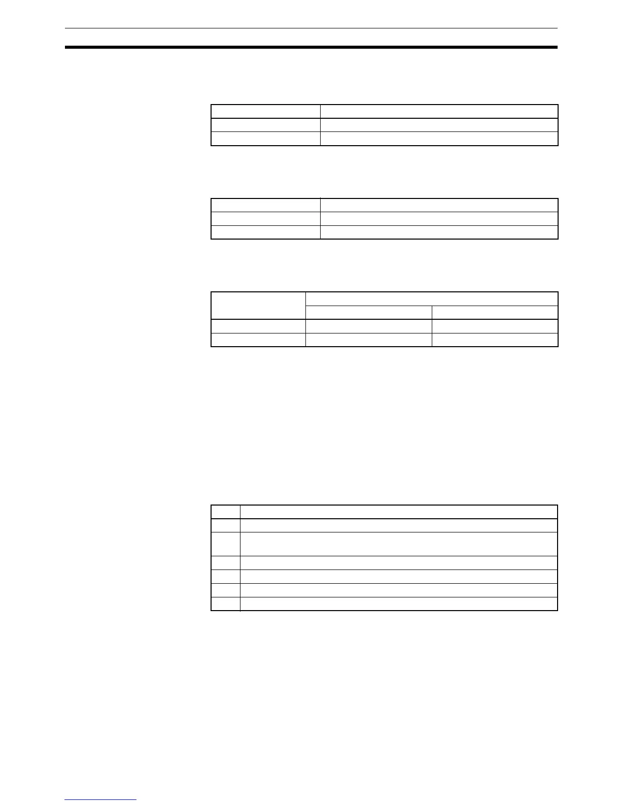
Pulse I/O Board: High-speed Counters 1 and 2
The following table shows the possible 8-digit BCD values for the PV of high-
speed counters 1 and 2 on a Pulse I/O Board.
Absolute Encoder Interface Board: High-speed Counters 1 and 2
The following table shows the possible values for the PV of absolute high-
speed counters 1 and 2.
High-speed Counter Board: High-speed Counters 1 to 4
The following table shows the possible 8-digit values (BCD or hexadecimal)
for the PV of high-speed counters 1 to 4 on a High-speed Counter Board.
High-speed Counter or
Pulse Output Status
(C=001)
If C is 001, PRV(62) reads the operating status of the specified high-speed
counter or pulse output and writes the data to D.
PRV(62) reads the same information stored in the AR and IR words allocated
for that purpose (AR 05 and AR 06 for the Pulse I/O Board or Absolute
Encoder Interface Board, IR 208 to IR 211 or IR 240 to IR 243 for the High-
speed Counter Board), but the allocated AR and IR words are refreshed just
once each cycle while PRV(62) reads the most up-to-date values.
Pulse I/O Board
The following table shows the function of bits in D for high-speed counters 1
and 2 or pulse outputs from ports 1 and 2 on a Pulse I/O Board. Bits not listed
in the table are not used and will always be 0.
Absolute Encoder Interface Board
For absolute high-speed counters 1 and 2, Bit 00 of D indicates the compari-
son status (0: Stopped; 1: Comparing). The other bits in D (01 through 15) are
not used and will always be 0.
Numeric range Possible values
Linear counting F838 8608 to 0838 8607
Ring counting 0000 0000 to 0006 4999
Mode Possible values
BCD mode 0000 0000 to 0000 4095
360° mode 0000 0000 to 0000 0359
Numeric range Possible values
BCD format Hexadecimal format
Linear counting F838 8608 to 0838 8607 F800 0000 to 07FF FFFF
Ring counting 0000 0000 to 0838 8607 0000 0000 to 07FF FFFF
Bit Function
00 High-speed counter comparison status. (0: Stopped; 1: Comparing)
01 High-speed counter underflow/overflow.
(0: Normal; 1: Underflow/Overflow occurred.)
04 Deceleration of pulse frequency. (0: Not specified; 1: Specified.)
05 Total number of pulses specified. (0: Not specified; 1: Specified.)
06 Pulse output completed. (0: Not completed; 1: Completed)
07 Pulse output status (0: Stopped; 1: Outputting)