EasyManua.ls Logo

Omron CQM1H - PROGRAM User Manual

Omron CQM1H - PROGRAM
602 pages
To Next Page IconTo Next Page
To Previous Page IconTo Previous Page
Page #307 background imageLoading...
Page #307 background image
282
Comparison Instructions Section 5-19
5-19-2 TABLE COMPARE – TCMP(85)
Limitations DM 6144 to DM 6655 cannot be used for R.
Description When the execution condition is OFF, TCMP(85) is not executed. When the
execution condition is ON, TCMP(85) compares CD to the content of TB,
TB+1, TB+2, ..., and TB+15. If CD is equal to the content of any of these
words, the corresponding bit in R is set, e.g., if the CD equals the content of
TB, bit 00 is turned ON, if it equals that of TB+1, bit 01 is turned ON, etc. The
rest of the bits in R will be turned OFF.
Flags ER: The comparison table (i.e., TB through TB+15) exceeds the data
area.
Indirectly addressed EM/DM word is non-existent.
(Content of *EM/*DM word is not BCD, or the EM/DM area boundary
has been exceeded.)
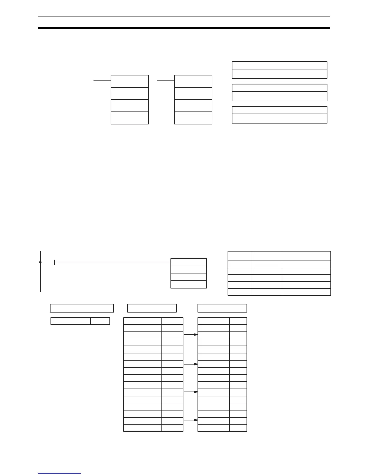
Example The following example shows the comparisons made and the results provided
for TCMP(85). Here, the comparison is made during each cycle when IR
00000 is ON.
CD: Compare data
IR, SR, DM, EM, HR, TIM/CNT, LR, #
TB: First comparison table word
IR, SR, DM, EM, HR, TIM/CNT, LR
Ladder Symbols
Operand Data Areas
R: Result word
IR, SR, DM, EM, HR, TIM/CNT, LR
TCMP(85)
CD
TB
R
@TCMP(85)
CD
TB
R
R: 216
DM 0000 0100 IR 21600 0
DM 0001 0200 IR 21601 0
DM 0002 0210 IR 21602 1
DM 0003 0400 IR 21603 0
DM 0004 0500 IR 21604 0
DM 0005 0600 IR 21605 0
DM 0006 0210 IR 21606 1
DM 0007 0800 IR 21607 0
DM 0008 0900 IR 21608 0
DM 0009 1000 IR 21609 0
DM 0010 0210 IR 21610 1
DM 0011 1200 IR 21611 0
DM 0012 1300 IR 21612 0
DM 0013 1400 IR 21613 0
DM 0014 0210 IR 21614 1
DM 0015 1600 IR 21615 0
00000
Compare the data in IR 001
with the given ranges.
Address Instruction Operands
00000 LD 00000
00001 TCMP(85)
001
DM 0000
216
TCMP(85)
001
DM 0000
216
IR 001 0210
CD: 001 Upper limits

Table of Contents

Question and Answer IconNeed help?

Do you have a question about the Omron CQM1H - PROGRAM and is the answer not in the manual?

Omron CQM1H - PROGRAM Specifications

General IconGeneral
I/O CapacityUp to 512 points
Power Supply100 to 240 VAC, 50/60 Hz or 24 VDC (depending on model)
Instruction SetBasic and advanced instructions
Operating Temperature0 to 55°C
Program Capacity7.2K to 15.2K steps
Communication PortsRS-232C
Expansion SlotsUp to 3 expansion units
TypeProgrammable Logic Controller (PLC)
CPU TypeRISC
Program Memory7.2K to 15.2K steps
I/O Points512 max
Expansion CapabilityUp to 3 expansion units
Data MemoryRAM (battery backup)

Summary

PRECAUTIONS

1 Intended Audience

Specifies the target personnel for this manual, requiring knowledge of electrical systems and FA systems.

2 General Precautions

Outlines user responsibilities for operating the product according to specifications and consulting representatives for specific applications.

3 Safety Precautions

Details critical safety warnings related to I/O refreshing, touching internal components, disassembly, and power supply handling.

5 Application Precautions

Provides essential safety guidelines for using the PC System, including grounding, power handling, and unit mounting.

SECTION 1 PC Setup and Other Features

1-1 PC Setup

Explains operating parameters for CQM1H control, including default values and how to change them.

SECTION 2 Inner Boards

2-1 High-speed Counter Board

Describes the functions, input modes, comparison operations, and external outputs of the High-speed Counter Board.

2-2 Pulse I/O Board

Details the Pulse I/O Board's support for two pulse inputs and two pulse outputs, including input modes and interrupts.

SECTION 3 Memory Areas

3-1 Memory Area Structure

Explains the memory areas used by the CQM1H PC, including IR, Work, Controller Link status, MACRO operand, Inner Board, Analog, High-speed Counter, and EM areas.

SECTION 4 Ladder-diagram Programming

4-1 Basic Procedure

Outlines the fundamental steps for writing a program, including obtaining I/O lists and drawing ladder diagrams.

4-4 Controlling Bit Status

Details instructions for controlling individual bit status: OUTPUT, OUTPUT NOT, SET, RESET, DIFFERENTIATE UP/DOWN, KEEP.

4-6 Programming Precautions

Provides essential precautions for drawing clear ladder diagrams and inputting programs, emphasizing instruction order and TR bits.

4-7 Program Execution

Describes the CPU Unit's program scan from top to bottom, checking conditions, and executing instructions.

SECTION 5 Instruction Set

SECTION 6 Host Link Commands

6-1 Host Link Command Summary

Provides a summary table of Host Link commands available for CQM1H communications.

6-4 Command and Response Formats

Details the formats for commands issued from the host computer and responses received from the PC.

6-5 Host Link Commands

Lists and describes various Host Link commands for reading and writing data in IR, SR, LR, HR, DM, EM, and AR areas.

SECTION 7 CPU Unit Operation and Processing Time

7-1 CPU Unit Operation

Explains the overall operation flowchart of the CQM1H CPU Unit and defines cycle time.

7-2 Power Interruptions

Details the CPU Unit's behavior during power interruptions and momentary power supply failures.

7-3 Cycle Time

Explains the processes involved in a single execution cycle and their respective processing times.

SECTION 8 Troubleshooting

8-2 Programming Console Operation Errors

Lists common error messages encountered when using the Programming Console and their appropriate responses.

Appendix A Programming Instructions

5-8 Ladder Diagram Instructions

Explains basic instructions like LOAD, AND, OR, and their combinations, including logic block instructions.

5-9 Bit Control Instructions

Covers instructions for controlling individual bit status: OUT, OUT NOT, SET, RESET, DIFU, DIFD, KEEP.

5-14 User Error Instructions: FAILURE ALARM AND RESET – FAL(06) and SEVERE FAILURE ALARM – FALS(07)

Describes instructions for outputting error numbers for operation, maintenance, and debugging, including non-fatal and fatal errors.

5-16 Timer and Counter Instructions

Details instructions for managing timers and counters, including TIM, TIMH, CNT, CNTR, TTIM, STIM, and CTBL.

5-29 Network Instructions

Explains instructions for communicating with other PCs via the Controller Link System, including SEND, RECV, and CMND.

5-30 Communications Instructions

Details instructions for serial communications, including RECEIVE (RXD), TRANSMIT (TXD), CHANGE SERIAL PORT SETUP (STUP), and PROTOCOL MACRO (PMCR).

Related product manuals