389
Special Instructions Section 5-28
Diagnostics Output There are two ways to output the bit address of the OFF condition detected in
the logic diagnostics condition.
1,2,3... 1. Bit address output (used when bit 15 of C is OFF).
Bit 15 of D indicates whether or not bit address information is stored in
D+1. If there is, bit 14 of D indicates whether the input condition is normally
open or closed.
D+1 contains the bit address code of the input condition, as shown below.
The word addresses, bit numbers, and TIM/CNT numbers are in binary.
Note a) *For the TIM/CNT area, bit 09 of D+1 indicates whether the num-
ber is a timer or counter. A 0 indicates a timer, and a 1 indicates a
counter.
b) The status of the leftmost bit of the bit number (bit 03) is reversed.
Example: If D + 1 contains 1000 0110 0100 1000, IR 10000 would be in-
dicated as follows:
2. Bit address and message output (selected when bit 15 of C is ON).
Bit 15 of D indicates whether or not there is bit address information stored
in D+1 to D+3. If there is, bit 14 of D indicates whether the input condition
is normally open or closed. Refer to the following table.
Words D+5 to D+8 contain information in ASCII that are displayed on a Pe-
ripheral Device along with the bit address when FPD(––) is executed.
Words D+5 to D+8 contain the message preset by the user as shown in the
following table.
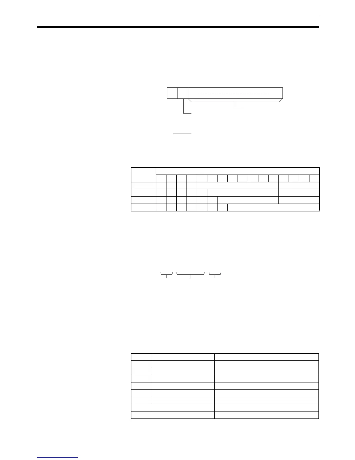
Data Area D+1 bit status
15 14 13 12 11 10 09 08 07 06 05 04 03 02 01 00
IR, SR 1 0 0 0 Word address Bit number
HR 1 0 0 1 1 Word address Bit number
LR 1 0 0 1 0 0 Word address Bit number
TIM/CNT* 1 0 0 1 0 1 * Timer or counter number
Word Bits 15 to 08 Bits 07 to 00
D+1 20 = space First ASCII character
D+2 Second ASCII character Third ASCII character
D+3 Fourth ASCII character Fifth ASCII character
D+4 2D = “–” “0”=normally open, “1”=normally closed
D+5 First ASCII character Second ASCII character
D+6 Third ASCII character Fourth ASCII character
D+7 Fifth ASCII character Sixth ASCII character
D+8 Seventh ASCII character Eighth ASCII character
15 14 13 00D:
Not used.
Input condition
0 (OFF): Normally open
1 (ON): Normally closed
Bit address information
0 (OFF): Not recorded in D+1.
1 (ON): Recorded in D+1.
1000 0110 0100 1000
IR $64 = 100 Bit 00 (inverting status of bit 03)