428
Advanced I/O Instructions Section 5-31
R and R+1 are not in the same data area. (When the CQM1H is set to
receive 8-digit data.)
SR 25410: ON while DSW(87) is being executed.
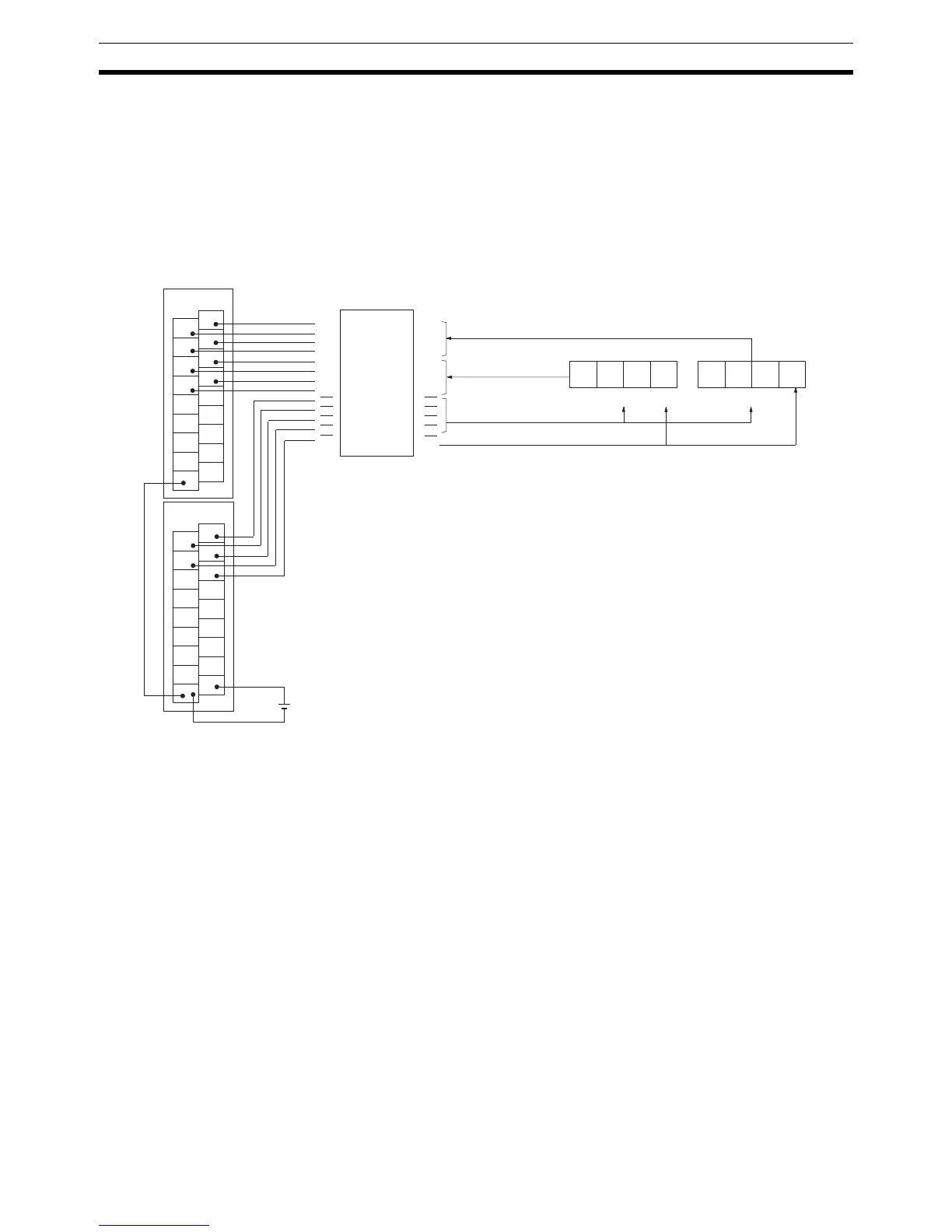
Hardware Connect the digital switch and the Input and Output Units as shown in the dia-
gram below. In the diagram, an 8-digit input is shown. When using a 4-digit
input, connect D0 through D3 from the digital switch to input points 0 through
3. In either case, output point 5 will be turned ON when one round of data is
read, but there is no need to connect output point 5 unless required for the
application.
1
3
5
7
9
11
13
15
COM
0
2
4
6
8
10
12
14
COM
ID212
1
3
5
7
9
11
13
15
COM
0
2
4
6
8
10
12
14
COM
OD212
D
0
D
1
D
2
D
3
D
0
D
1
D
2
D
3
CS
0
CS
1
CS
2
CS
3
RD
Interface
A7E data line
leftmost digits
To A7E chip selection
To A7E RD terminal
Leftmost digits
A7E
Rightmost digits
A7E data line rightmost digits
Input Unit
Output Unit
Note An interface to convert signals from 5 V to 24 V is
required to connect an A7E digital switch.
D
0
D
1
D
2
D
3
D
0
D
1
D
2
D
3
CS
0
CS
1
CS
2
CS
3
RD