EasyManuals Logo

Omron CQM1H - PROGRAM User Manual

Omron CQM1H - PROGRAM
602 pages
To Next Page IconTo Next Page
To Previous Page IconTo Previous Page
Page #457 background imageLoading...
Page #457 background image
432
Advanced I/O Instructions Section 5-31
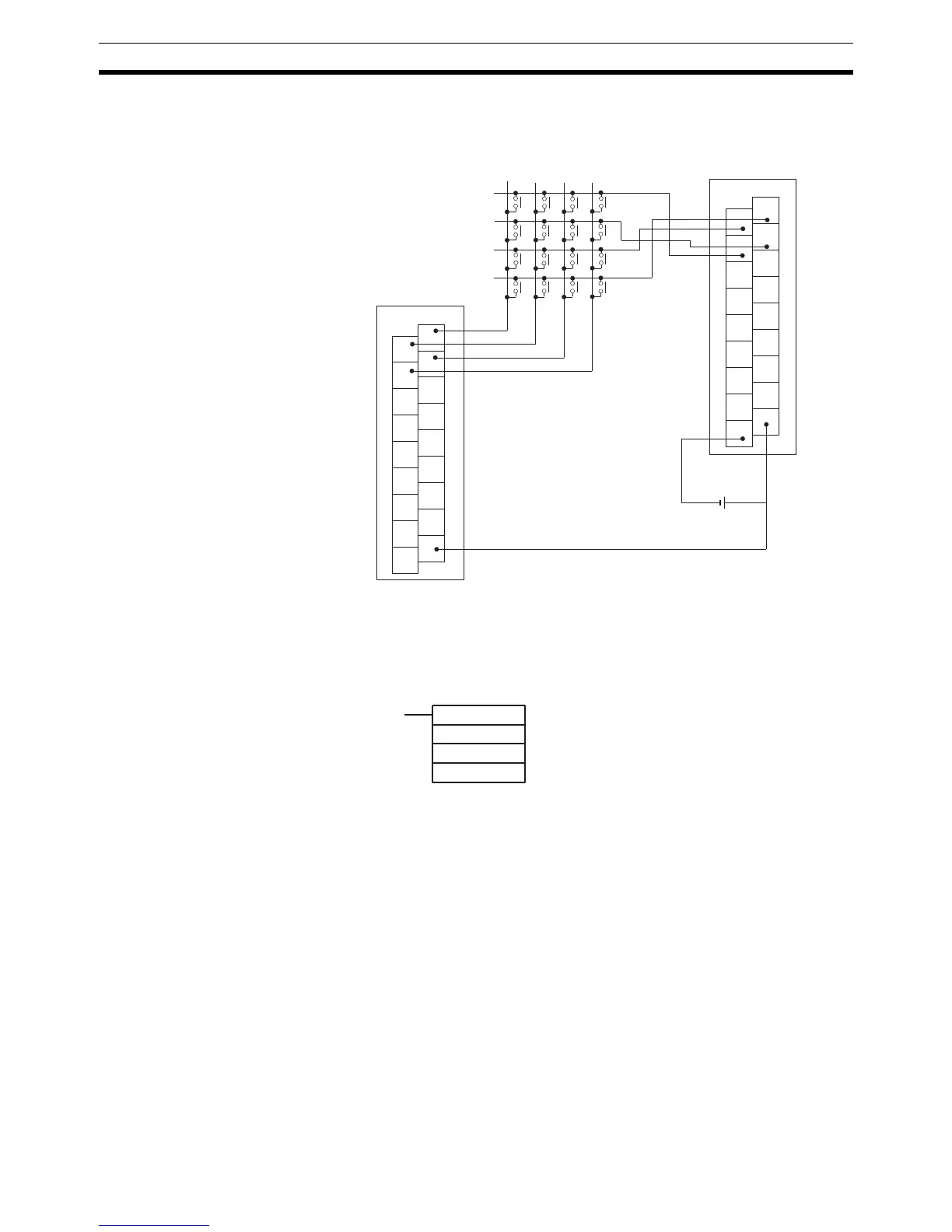
Hardware Prepare the hexadecimal keyboard, and connect the 0 to F numeric key
switches, as shown below, to input points 0 through 3 and output points 0
through 3. Output point 4 will be turned ON while any key is being pressed,
but there is no need to connect it.
The inputs can be connected to the input terminals on the CPU Unit or a DC
Input Unit with 8 or more input points and the outputs can be connected from
a Transistor Output Unit with 8 points or more.
Using the Instruction
1
3
5
7
9
11
13
15
COM
0
2
4
6
8
10
12
14
COM
ID212
1
3
5
7
9
11
13
15
COM
0
2
4
6
8
10
12
14
COM
OD212
C
8
4
0
D
9
5
1
E
A
6
2
F
B
3
7
Input Unit
Output Unit
HKY
IW
0W
D
IW: Input word
OW: Control signal output word
D: First register word

Table of Contents

Questions and Answers:

Question and Answer IconNeed help?

Do you have a question about the Omron CQM1H - PROGRAM and is the answer not in the manual?

Omron CQM1H - PROGRAM Specifications

General IconGeneral
I/O CapacityUp to 512 points
Power Supply100 to 240 VAC, 50/60 Hz or 24 VDC (depending on model)
Instruction SetBasic and advanced instructions
Operating Temperature0 to 55°C
Program Capacity7.2K to 15.2K steps
Communication PortsRS-232C
Expansion SlotsUp to 3 expansion units
TypeProgrammable Logic Controller (PLC)
CPU TypeRISC
Program Memory7.2K to 15.2K steps
I/O Points512 max
Expansion CapabilityUp to 3 expansion units
Data MemoryRAM (battery backup)

Related product manuals