EasyManuals Logo

Omron CQM1H - PROGRAM User Manual

Omron CQM1H - PROGRAM
602 pages
To Next Page IconTo Next Page
To Previous Page IconTo Previous Page
Page #534 background imageLoading...
Page #534 background image
509
Troubleshooting Flowcharts Section 8-7
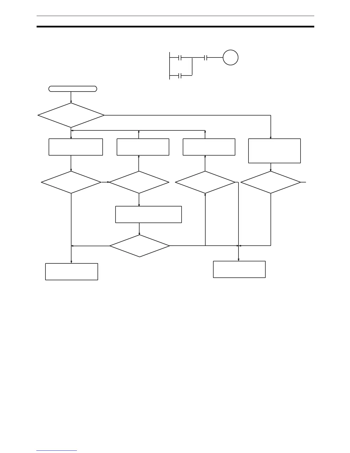
I/O Check The I/O check flowchart is based on the following ladder diagram section.
10500
00002
(LS1)
00003
(LS2)
SOL1 malfunction.
SOL1
10500
Ye s
Monitor the ON/OFF
status of IR 10500
with a Peripheral
Device.
No
Is the IR 10500 out-
put indicator operat-
ing normally?
Check the voltage at the
IR 10500 terminals.
Wire correctly. Replace terminal
connector.
Operation OK?
Is terminal
block making prop-
er contact?
Disconnect the external wires
and check the conductivity of
each wire.
Operation OK?
Start
Is output wiring
correct?
No
Ye s
Check output device
SOL1.
Replace the Output
Unit.
Ye s
No
No
Ye s
No
NoYe s
Ye s
A
To
next
page
(See note)
The error may be due to a blown fuse
or output transistor malfunction.
Operation OK?

Table of Contents

Questions and Answers:

Question and Answer IconNeed help?

Do you have a question about the Omron CQM1H - PROGRAM and is the answer not in the manual?

Omron CQM1H - PROGRAM Specifications

General IconGeneral
I/O CapacityUp to 512 points
Power Supply100 to 240 VAC, 50/60 Hz or 24 VDC (depending on model)
Instruction SetBasic and advanced instructions
Operating Temperature0 to 55°C
Program Capacity7.2K to 15.2K steps
Communication PortsRS-232C
Expansion SlotsUp to 3 expansion units
TypeProgrammable Logic Controller (PLC)
CPU TypeRISC
Program Memory7.2K to 15.2K steps
I/O Points512 max
Expansion CapabilityUp to 3 expansion units
Data MemoryRAM (battery backup)

Related product manuals